After the shearing machine, the feeding and cutting conveyor line

A shearing machine and conveying line technology, applied in metal processing equipment, feeding devices, manufacturing tools, etc., can solve the problems that the back gauge cannot stop the material, the precision of the cutting surface is extremely high, and the welding surface of the plate requires high precision. To achieve the effect of ensuring dimensional stability

Active Publication Date: 2016-07-06
KUSN BAOJIN LASER TAILOR WELDED
View PDF9 Cites 0 Cited by
  • Summary
  • Abstract
  • Description
  • Claims
  • Application Information

AI Technical Summary

Problems solved by technology

However, laser tailor welding requires high precision on the welding surface of the plate, and extremely high precision on the cutting surface.
[0003] At present, when the existing shearing machine cuts larger products, the rear gauge cannot be blocked due to material sagging, which affects the shear size and the accuracy of the cut surface

Method used


Image

  • After the shearing machine, the feeding and cutting conveyor line
  • After the shearing machine, the feeding and cutting conveyor line

Examples


Embodiment Construction

[0018] The technical solutions of the present invention will be further described below in conjunction with the accompanying drawings and through specific implementation methods.

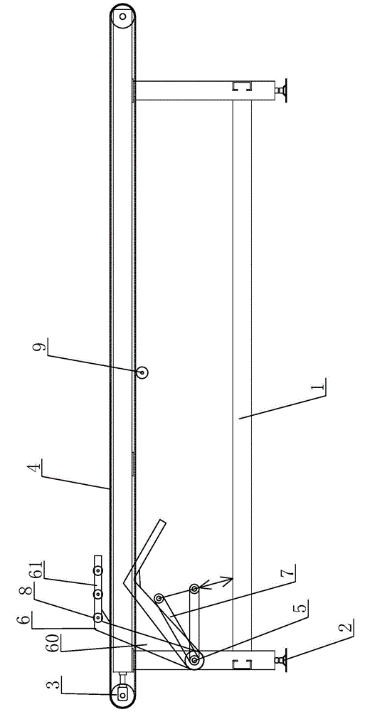
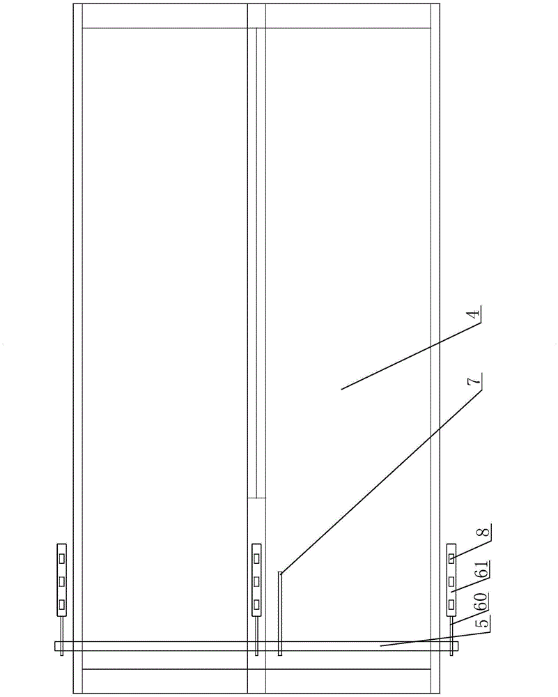
[0019] see figure 1 and figure 2 as shown, figure 1 It is a side view of the feeding and shearing conveying line after the shearing machine provided in Embodiment 1 of the present invention; figure 2 It is a top view of the delivery line for the rear discharge support shear of the shearing machine provided in Embodiment 1 of the present invention.

[0020] In this embodiment, a shearing conveyor line for the rear of the shearing machine includes a frame 1, the four corners of the bottom of the frame 1 are provided with adjustable height cup feet 2, and the two ends of the frame 1 are installed There is a conveyor wheel 3, and a conveyor belt 4 is connected between the conveyor wheels 3 at both ends. The conveyor belt 4 is composed of two narrow belts arranged at intervals. The conveyor belt 4 ...


PUM


Abstract

The invention discloses a plate shearer rear discharging bearing and shearing conveying line. The plate shearer rear discharging bearing and shearing conveying line comprises a machine frame; two ends of the machine frame are provided with conveying wheels; a conveying belt is connected between the conveying wheels at two ends; the conveying belt is connected with a driving component through a transmission assembly; one end of the machine frame is provided with a rotary shaft which horizontally penetrates the internal conveying belt; at least two ends of the rotary shaft are both provided with a supporting arm; the supporting arms comprise supporting plates; end portions of the supporting plates bend towards one side to be provided with bearing plates; a transmission plate is fixed on the rotary shaft; the transmission plate is connected with a driving air cylinder; the bearing plates are parallel to the conveying belt when the supporting arms are ejected. According to the plate shearer rear discharging bearing and shearing conveying line, the driving air cylinder drives the transmission plate and accordingly drives the rotary shaft to rotate and rotation of the rotary shaft drives the supporting arms to perform rotation in fixed angles to lift up plates on the conveying line, so that rear blocking materials cannot block materials caused by material drooping is avoided and the stable shearing plate size and the section angle accuracy are guaranteed.

Description

technical field [0001] The invention relates to a conveying line of a shearing machine, in particular to a conveying line of a shearing machine with a rear discharge support for the shearing machine. Background technique [0002] As a new high-tech, laser tailor welding has shown its infinite unique charm to people. It has the characteristics of high welding quality, high quality, aesthetics and flux-free environmental protection. It also breaks through the shackles of some high-alloy materials and processes. However, laser tailor welding requires high precision on the welding surface of the plate, and extremely high precision on the cutting surface. [0003] At present, when the existing shearing machine cuts larger products, the rear gauge cannot be blocked due to material sagging, which affects the shear size and the accuracy of the cut surface. Contents of the invention [0004] The object of the present invention is to provide a shearing conveying line for the rear o...

Claims


Application Information

Patent Timeline
Patent Type & Authority Patents(China)
IPC IPC(8): B21D43/28
Inventor 王传喜
Owner KUSN BAOJIN LASER TAILOR WELDED
Why Eureka
Try Eureka