Two-direction mechanical locking hydraulic cylinder

A technology of hydraulic cylinders and mechanical locks, applied in the field of hydraulic cylinders, can solve the problems of high requirements on machining accuracy of piston rod sleeves, difficult to ensure self-locking reliability, and inability to meet high-precision locking and other problems, so as to achieve broad prospects for promotion and use. Avoid the effect of being unable to unlock and lock reliably

Active Publication Date: 2014-08-27
CSIC ZHONGNAN EQUIP
View PDF6 Cites 18 Cited by
  • Summary
  • Abstract
  • Description
  • Claims
  • Application Information

AI Technical Summary

Problems solved by technology

However, after this type of hydraulic cylinder is self-locking, the high-pressure oil in the rodless chamber or the rod chamber of the hydraulic cylinder is prone to infiltration, and the locking pressure drops, resulting in displacement of the piston, which cannot meet the requirements of high-precision locking.
[0003] In the existing self-locking hydraulic cylinders, there are also some methods of hydraulically controlling the piston rod sleeve and the piston rod to carry out interference fit, locking the piston rod to achieve locking, but the processing accuracy of the piston rod sleeve is high, and it is difficult to guarantee The reliability of self-locking, in addition, there are defects of short service life and high production cost

Method used


Image

  • Two-direction mechanical locking hydraulic cylinder

Examples


Embodiment Construction

[0029] The present invention will be described in detail below with reference to the accompanying drawings and examples.

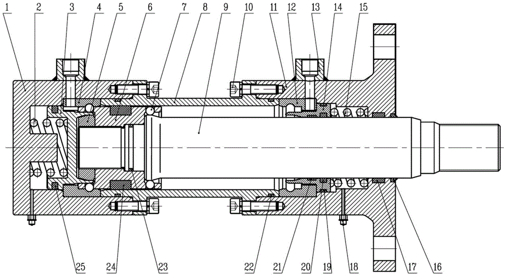
[0030] as attached figure 1 As shown, the two-way mechanical locking hydraulic cylinder of the present invention includes a cylinder bottom 1, a rear spring 2, a rear spring seat 3, a rear locking seat 4, a lock nut 5, a piston 6, a steel ball 7, a cylinder barrel 8, a piston rod 9. Bolt 10, cylinder head 11, front locking seat 12, oil port 13, front spring seat 14, front spring 15, dustproof ring 16, cylinder head sealing ring 17, oil drain port 18, front spring seat shaft sealing ring 19. Front spring seat hole seal ring 20, front spring seat support ring 21, cylinder barrel seal ring 22, inner seal ring 23, piston seal ring 24 and rear spring seat seal ring 25.

[0031] One end of the cylinder bottom 1 is provided with a coaxial annular groove and a spring guide post, and the outer peripheral surface of the cylinder bottom 1 is provided with a cylinder...


PUM


Abstract

The invention discloses a two-direction mechanical locking hydraulic cylinder, and belongs to the technical field of air cylinders. When high-pressure oil is injected from an oil port in the bottom of the cylinder, high pressure oil pushes a rear spring base to compress a rear spring, and rightward pushing force is provided for a piston and a piston rod at the same time; after a rear spring base moves leftwards by a certain distance, a steel ball is disengaged from a rear locking base, unlocking is achieved, and the piston rod begins to stretch out. When the piston is close to a front locking base, the steel ball pushes a front spring base to compress a front spring, the steel ball enters a groove in the front locking base, the front spring base is inserted into the portion below the steel ball under the action of spring force so as to support the steel ball, and locking is achieved. In this way, even when two working chambers completely release pressure, under the action of the spring force, the piston and the piston rod can be firmly locked at the two end limiting positions. According to the two-direction mechanical locking hydraulic cylinder, stable mechanical locking can be achieved at the top dead center and the bottom dead center, pressure can be completely released after locking, and the service life of the hydraulic cylinder can be prolonged.

Description

technical field [0001] The invention relates to a hydraulic cylinder, in particular to a two-way mechanical locking hydraulic cylinder, which belongs to the technical field of hydraulic cylinders. Background technique [0002] At present, the self-locking hydraulic cylinder often adopts the hydraulic lock of the one-way valve type to realize the self-locking of the hydraulic cylinder at different positions. However, after self-locking of this type of hydraulic cylinder, the high-pressure oil in the rodless chamber or the rod chamber of the hydraulic cylinder is prone to infiltration, and the locking pressure drops, resulting in displacement of the piston, which cannot meet the requirements of high-precision locking. [0003] In the existing self-locking hydraulic cylinders, there are also some methods of hydraulically controlling the piston rod sleeve and the piston rod to carry out interference fit, locking the piston rod to achieve locking, but the processing accuracy of t...

Claims


Application Information

Patent Timeline
Patent Type & Authority Applications(China)
IPC IPC(8): F15B15/26F15B15/14
Inventor 杜浩斌陈向灵雷辉虎唐瑞郭明金国俊王永华
Owner CSIC ZHONGNAN EQUIP
Why Eureka
Try Eureka