Electronic expansion valve and insertion component thereof

A technology for electronic expansion valves and components, applied in refrigeration components, lift valves, valve details, etc., can solve the problems of refrigerant leakage, easy collision with each other, insufficient tightening force, etc., to improve the use effect, avoid contact collision, The effect of easy assembly

Active Publication Date: 2014-08-27
ZHEJIANG SANHUA CLIMATE & APPLIANCE CONTROLS GRP CO LTD
View PDF5 Cites 2 Cited by
  • Summary
  • Abstract
  • Description
  • Claims
  • Application Information

AI Technical Summary

Problems solved by technology

[0005] Due to the limited installation space, the distance between the four pins 06 is only about 4mm, and the terminal 05 is connected to one end of the pin 06 sintered and fixed, that is to say, one end of the terminal 05 is fixed, and the maximum distance between each terminal 05 It is only about 4mm; the diameter of terminal 05 is usually about 2.7mm, and the distance between adjacent two terminals 05 is relatively short. When the leads 04 connected to the other end of electronic 05 are entangled with each other, it is easy to Collide with each other, and then produce a short circuit, affecting the normal use of the motor 03
[0006] In addition, the existing electronic expansion valve has many components, and the cover 02 and the shell 01 are assembled through threaded connection, the tightening force is not enough, and there is a risk of refrigerant leakage

Method used


Image

  • Electronic expansion valve and insertion component thereof
  • Electronic expansion valve and insertion component thereof
  • Electronic expansion valve and insertion component thereof

Examples


Embodiment Construction

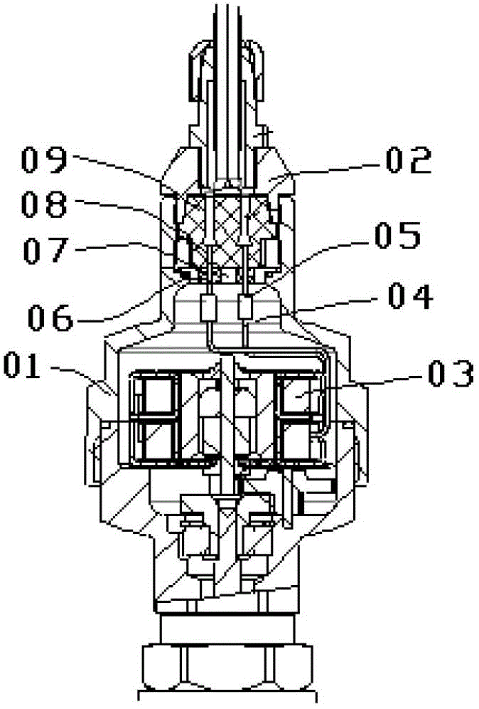
[0037] The core of the present invention is to provide a plug-in assembly of an electronic expansion valve, which can avoid contact and collision between adjacent terminals and avoid short circuit.

[0038] Another core of the present invention is to provide an electronic expansion valve with the above-mentioned plug-in assembly, which has high connection reliability and is safer and more convenient to use.

[0039] In order to enable those skilled in the art to better understand the solution of the present invention, the present invention will be further described in detail below in conjunction with the accompanying drawings and specific embodiments.

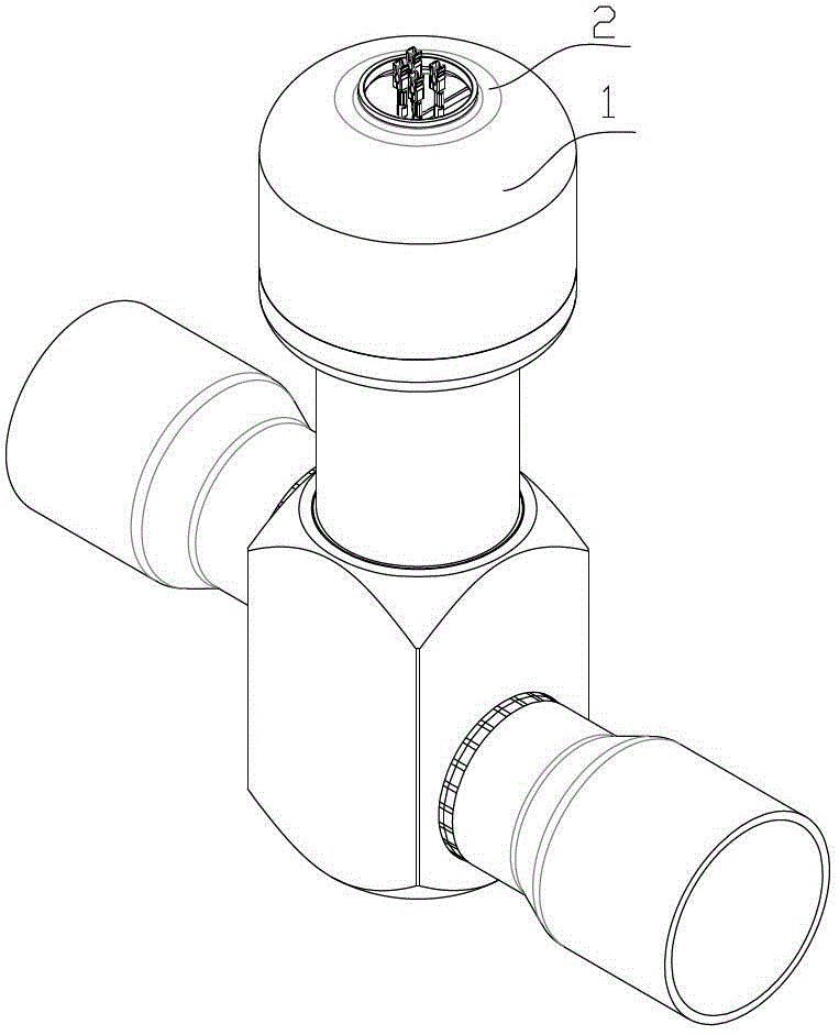
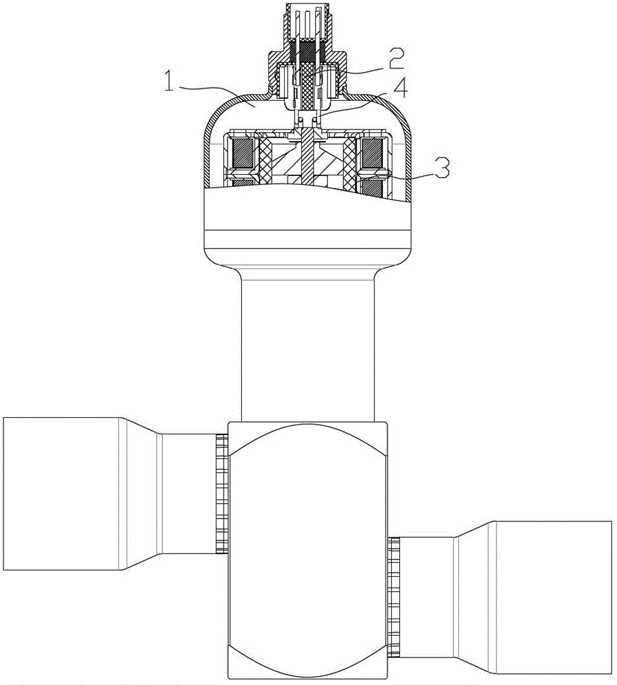
[0040] Please refer to figure 2 and image 3 , figure 2 It is a schematic diagram of the three-dimensional structure of the electronic expansion valve provided by the present invention in a specific embodiment; image 3 for figure 2 Partial cross-sectional view of the front structure of the electronic expansion valve sho...


PUM


Abstract

The invention provides an electronic expansion valve and an insertion component thereof capable of preventing the short circuit caused by collision among terminals, and improving the using reliability. The insertion component comprises a connection socket and a contact pin, wherein the connection socket is hermetically connected with a shell of the electronic expansion valve, the contact pin is connected with an external control piece, and a valve chamber of a motor is built-in in the shell; the connection socket is provided with a sealing cavity communicated with the valve chamber, the sealing cavity is sleeved with an insulation sleeve, the insulation sleeve is provided with mounting positions corresponding to the terminals of the motor and all the mounting positions are alternately connected in an insulation way; the insulation sleeve is further provided with a connecting hole provided for the contact pin to pass through, one end of the contact pin penetrates through the connecting hole and is connected with the terminal, and the other end of the contact pin protrudes out the sealing cavity so as to form a connecting end used for being connected with the external control piece. All terminals of the insulation sleeve provided by the invention are provided with the corresponding positions, so that all the terminals are separated mutually, the short circuit caused by the touch collision among the terminals can be prevented, and the electronic expansion valve and the insertion component are safer and reliable to use.

Description

technical field [0001] The invention relates to the technical field of valve body connection, in particular to a plug assembly of an electronic expansion valve. The present invention also relates to an electronic expansion valve using the above-mentioned plug-in assembly. Background technique [0002] As the shortcomings of thermal expansion valves become more and more obvious, electronic expansion valves are increasingly used in existing large refrigeration units. [0003] Please refer to figure 1 , figure 1 It is a schematic cross-sectional structure diagram of an arrangement mode of an electronic expansion valve in the prior art. [0004] The existing electronic expansion valve includes a casing 01 and a cover 02. The cover 02 is screwed to the end of the casing 01; the casing 01 is set in a hollow structure, and the hollow part constitutes a valve cavity, and the motor 03 is built in the valve cavity; the motor 03 is connected to There is a lead wire 04, which has a ...

Claims


Application Information

Patent Timeline
Patent Type & Authority Applications(China)
IPC IPC(8): F16K1/00F16K31/04F25B41/06F25B41/34
CPCF16K1/00F16K31/046F25B41/31
Inventor 不公告发明人
Owner ZHEJIANG SANHUA CLIMATE & APPLIANCE CONTROLS GRP CO LTD
Why Eureka
Try Eureka