
Ball-roller mixed rolling positive pressure heavy-load guide rail pair

A technology of positive pressure and guide rail pairs, which is applied in the direction of rolling resistance optimization, linear motion bearings, large fixed members, etc., can solve problems that affect the motion accuracy of high-end CNC machine tools, reduce the use efficiency of linear guide rails, and increase the noise of linear guide rails. , to achieve the effect of long-term operation, improvement of motion accuracy and use efficiency, and enhanced bearing capacity

Pending Publication Date: 2019-07-05
SUZHOU HUAZHENG IND TECH CO LTD
View PDF5 Cites 1 Cited by
  • Summary
  • Abstract
  • Description
  • Claims
  • Application Information

AI Technical Summary

Problems solved by technology

Existing linear guide rails are usually four-row ball type and four-row roller type used alone. As linear guide rails are widely used in high-end CNC machine tools, linear guide rails often need to withstand large positive pressure when they are in the load-bearing area. With the increase of positive pressure, the friction resistance of the linear guide gradually increases. At the same time, affected by the resistance, the linear guide will fluctuate and vibrate, which will affect the motion accuracy of high-end CNC machine tools. Due to the gradual increase of friction resistance, The motion noise of the linear guide gradually increases, resulting in a decrease in the efficiency of the linear guide

Method used


Image

  • Ball-roller mixed rolling positive pressure heavy-load guide rail pair
  • Ball-roller mixed rolling positive pressure heavy-load guide rail pair
  • Ball-roller mixed rolling positive pressure heavy-load guide rail pair

Examples


Embodiment Construction

[0023] In view of the deficiencies in the prior art, the case has been studied for a long time and a large amount of practice, and the technical scheme of the present invention can be proposed. The technical solutions in the embodiments of the present invention will be clearly and completely described below in conjunction with the accompanying drawings in the embodiments of the present invention.

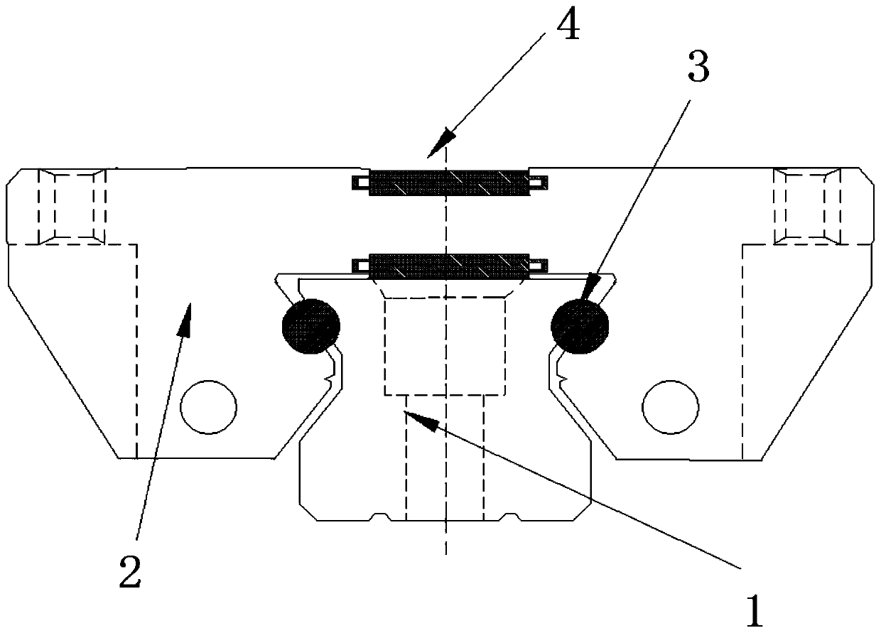
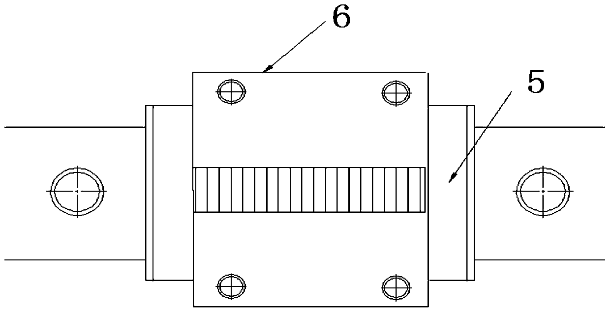
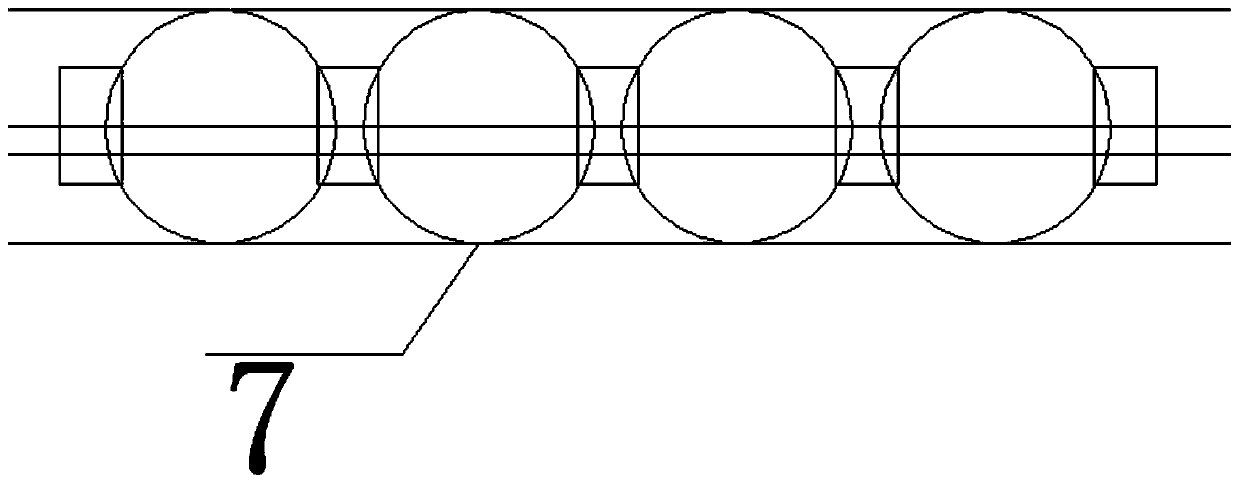
[0024] figure 1 It is a cross-sectional view of the ball and column mixed rolling positive pressure heavy-duty guide rail pair; figure 2 It is a schematic diagram of the structure of the ball and column mixed rolling positive pressure heavy-duty guide rail pair; image 3 is a cutaway view of the ball cage; Figure 4 It is a sectional view of the roller cage. like Figure 1 to Figure 4 As shown, the ball and column mixed rolling positive pressure heavy-duty guide rail pair provided in the embodiment of the present invention includes: a guide rail 1 and a slider 2 arranged on the...


PUM


Abstract

The invention discloses a ball-roller mixed rolling positive pressure heavy-load guide rail pair. The guide rail pair comprises a guide rail (1) and a sliding block (2) arranged on the guide rail (1);the two sides of the guide rail (1) are provided with rolling driving surfaces correspondingly to be matched with balls (3); the top surface of the guide rails (1) is a main moving driving surface which bears the positive pressure of a moving heavy-load object and is provided with a row of large rollers (4); two returning devices (5) are arranged at the left end and the right end of the sliding block (2) correspondingly, the sliding block (2) and the returning devices (5) are used for forming two rows of ball circulation loops allowing the balls (3) to circularly move, and the sliding block (2) and the returning devices (5) are used for forming a row of roller circulation loop allowing the large rollers (4) to circularly move. According to the guide rail pair, the bearing capacity of a linear guide rail is improved, fluctuation vibration of the rolling resistance is reduced to the maximum degree, so that the friction noise of the linear guide rail is reduced, smooth and stable movement is achieved, and the movement precision and the use efficiency of the linear guide rail are improved to a new level.

Description

technical field [0001] The invention relates to the technical field of linear guide devices, in particular to a bead and column mixed rolling positive pressure heavy-duty guide rail pair. Background technique [0002] With the rapid development of the contemporary machinery industry, people's requirements for the efficiency, precision, and environment of machining are constantly improving. Linear guide rails have become an important part of machinery industry processing due to their advantages such as high transmission efficiency, good motion accuracy, environmental protection and energy saving. An irreplaceable and important part of the system. Linear guides can be divided into: ball linear guides and roller linear guides, which are used to support and guide moving parts, and perform reciprocating linear motion in a given direction. [0003] Linear guides have been widely used in high-end CNC machine tools due to their irreplaceable important characteristics. People pay mo...

Claims


Application Information

Patent Timeline
Patent Type & Authority Applications(China)
IPC IPC(8): B23Q1/01F16C29/04F16C33/38
CPCB23Q1/017F16C29/04F16C33/38Y02T10/86
Inventor 单宪民王善良
Owner SUZHOU HUAZHENG IND TECH CO LTD
Learn More