Buffer and limiting mechanism of plastic pulling and blowing machine

A limit mechanism, plastic technology, applied to other household appliances, household appliances, household components, etc., can solve the problems that affect the service life of the cylinder of the bottom mold, easy to be damaged, etc.

Pending Publication Date: 2018-09-21
汪微莎
View PDF2 Cites 0 Cited by
  • Summary
  • Abstract
  • Description
  • Claims
  • Application Information

AI Technical Summary

Problems solved by technology

However, this structure does not have a mechanism for limiting the top plate. When the bottom mold cylinder drives the top plate to move downward, the top plate will collide with the bottom mold cylinder and be easily damaged, thus seriously affecting the service life of the bottom mold cylinder.

Method used


Image

  • Buffer and limiting mechanism of plastic pulling and blowing machine
  • Buffer and limiting mechanism of plastic pulling and blowing machine
  • Buffer and limiting mechanism of plastic pulling and blowing machine

Examples


Embodiment Construction

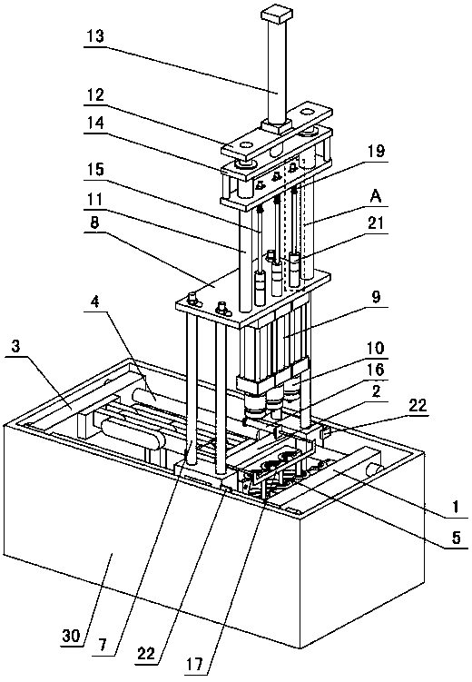
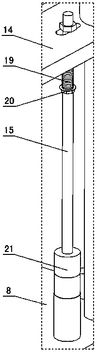
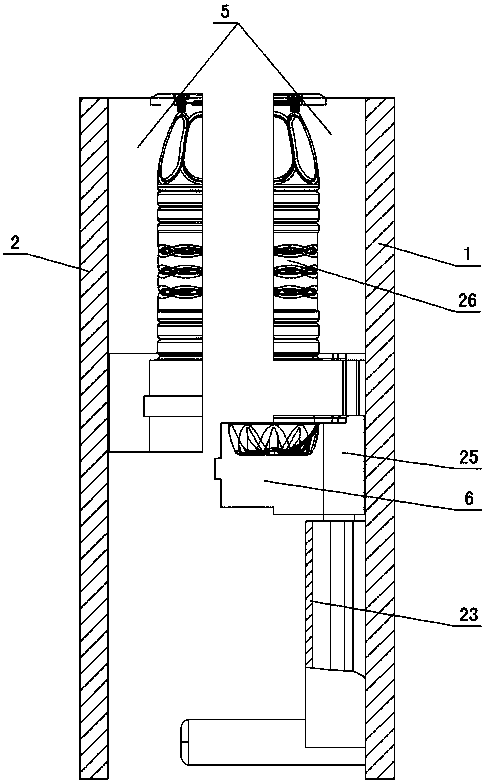
[0011] The invention relates to a buffer and limit mechanism of a plastic stretch blowing machine, such as figure 1 — Figure 4As shown, including a frame 30, a front formwork 1, a middle formwork 2 and a rear formwork 3 are arranged in the frame, and the front, middle and rear formworks are connected through guide rods 4, and a valve is respectively installed between the front formwork and the middle formwork. Mold 5, bottom mold 6 is set under the mold, mold opening and closing mechanism is set between middle template and rear template, bracket 7 and bottle pushing cylinder 16 are set on the middle template, fixing plate 8 is set on the bracket, and sealing cylinder 9 is installed under the fixing plate , the piston rod of the sealing cylinder is connected to the sealing blow joint 10, the support rod 11 is arranged on the fixed plate, the support plate 12 is arranged on the support rod, the stretching cylinder 13 is arranged on the support plate, and the piston rod of the s...


PUM


Abstract

The invention discloses a buffer and limiting mechanism of a plastic pulling and blowing machine. The buffer and limiting mechanism comprises the structure that a front mold plate, a middle mold plateand a rear mold plate are arranged in a rack; molds are arranged in the front mold plate and the middle mold plate; bottom molds are arranged below the molds; a mold opening / closure mechanism is arranged between the middle mold plate and the rear mold plate; a bracket and a bottle push cylinder are arranged on the middle mold plate; a fixing plate is arranged on the bracket; a sealing cylinder ismounted below the fixing plate, and is connected with a sealing blowing joint; a supporting rod is arranged on the fixing plate; a supporting plate is arranged on the supporting rod; a drawing cylinder is arranged on the supporting plate, and is connected with a mounting frame; a drawing rod is mounted below the mounting frame; the bottle push cylinder is connected with a bottle push plate. The buffer and limiting mechanism is characterized in that a buffer spring is arranged on the drawing rod; a fixing screw nut is arranged below the buffer spring; a buffer sleeve is arranged on the outer wall of the drawing rod, a bottom mold cylinder and bottom mold limiting blocks are arranged on the inner wall of the front mold plate, the bottom mold cylinder is connected with bottom mold mounting plates, the bottom molds are mounted on the bottom mold mounting plates, five-claw bottle bottoms are arranged in the bottom molds, the bottom mold limiting blocks are positioned on two sides of the bottom mold cylinder, the upper ends of the bottom mold limiting blocks are 10-30 mm higher than the bottom mold cylinder, and a hand pinching prevention sensor is arranged on the inner wall of the rack.

Description

technical field [0001] The invention relates to a plastic stretch-blow machine, in particular to a buffer and limit mechanism for a plastic stretch-blow machine. Background technique [0002] The plastic molding equipment used to process various hollow plastic containers, such as mineral water bottles, oil bottles, and cosmetic bottles, has a one-step method or a two-step method. The two-step method equipment includes an injection molding machine for processing bottle tubes, and a heater for heating the bottle tubes twice. And plastic stretch blowing machine, in which the plastic stretch blowing machine needs to drive the mounting frame through the stretching cylinder when the plastic stretching blowing machine is stretching and blowing the bottle tube, and then the mounting frame drives the stretching rod to stretch the bottle tube, and at the same time, the sealing cylinder Drive the sealing and blowing joint to seal the bottle tube, and blow high-pressure gas into the bot...

Claims


Application Information

Patent Timeline
IPC IPC(8): B29C49/10B29C49/42B29C49/48B29C49/70B29L22/00
CPCB29C49/10B29C49/42B29C49/48B29C49/70B29C2049/708B29L2031/7158B29C49/48185
Inventor 汪微莎
Owner 汪微莎
Why Eureka
Try Eureka