Spiral heat exchanger and manufacturing method thereof and air conditioner

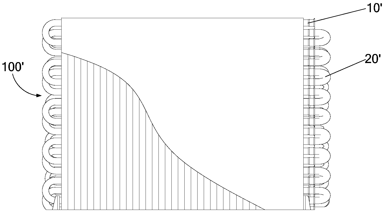
A manufacturing method and heat exchanger technology, which is applied in the field of air conditioners and spiral heat exchangers, can solve the problems of limited heat exchanger 100' heat transfer level, small heat exchanger frontal area, unfavorable production automation, etc., and achieve avoidance technology risk, avoid refrigerant leakage, and create simple and convenient effects

Inactive Publication Date: 2014-08-27
WUHAN REFRIGERATION EQUIP OF MIDEA GROUP
View PDF9 Cites 7 Cited by
  • Summary
  • Abstract
  • Description
  • Claims
  • Application Information

AI Technical Summary

Problems solved by technology

[0002] The heat exchangers used in existing household air conditioners are generally tube-fin heat exchangers, and most of them are planar heat exchangers. This structural form of heat exchanger has small windward area, multi-row heat exchange The problem of poor efficiency, in the current environment where the global awareness of energy conservation is gradually increasing, the energy efficiency of air-conditioning products is increasing year by year, however, if figure 1 As shown, the traditional structure of the existing planar tube-fin heat exchanger 100' limits the heat exchange level of the heat exchanger 100', and each of the existing planar tube-fin heat exchanger 100' The nozzle of the heat exchange tube 10' must be welded with connecting pipes such as the semicircular pipe 20', which is not conducive to production automation, and is prone to technical risks of refrigerant leakage due to poor welding of the nozzle

Method used


Image

  • Spiral heat exchanger and manufacturing method thereof and air conditioner
  • Spiral heat exchanger and manufacturing method thereof and air conditioner
  • Spiral heat exchanger and manufacturing method thereof and air conditioner

Examples


Embodiment Construction

[0044] In order to understand the above-mentioned purpose, features and advantages of the present invention more clearly, the present invention will be further described in detail below in conjunction with the accompanying drawings and specific embodiments. It should be noted that, in the case of no conflict, the embodiments of the present application and the features in the embodiments can be combined with each other.

[0045] In the following description, many specific details are set forth in order to fully understand the present invention. However, the present invention can also be implemented in other ways than described here. Therefore, the protection scope of the present invention is not limited by the specific implementation disclosed below. Example limitations.

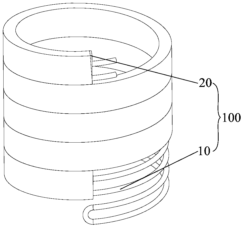
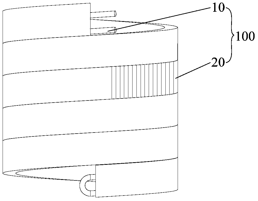
[0046] Refer to the attached Figures 2 to 5 Description A spiral heat exchanger 100 is provided according to some embodiments of the present invention.

[0047] Such as figure 2 As shown, a spiral heat e...


PUM


Abstract

The invention provides a spiral heat exchanger and a manufacturing method thereof and an air conditioner. The spiral heat exchanger comprises a heat exchange pipe and a plurality of fins, the heat exchange pipe is spirally wound to be cylindrical, the centers of the fins are provided with mounting holes matched with the heat exchange pipe, and the outer portion of the heat exchange pipe is sleeved with the fins at intervals through the mounting holes. Air can be sucked around the spiral heat exchanger; compared with a mode that a traditional plane-shaped heat exchanger can only suck air with one side, the windward area of the spiral heat exchanger is increased by 2-3 times, and integral heat exchange efficiency of the spiral heat exchanger is greatly improved; in addition, according to the spiral heat exchanger, a semicircular connecting pipe does not need to be welded to the heat exchange pipe, the bending process and cost of the semicircular pipe are reduced, the technical risk of refrigerant leakage caused by poor pipe opening welding is avoided, the manufacturing of the spiral heat exchanger becomes simple and convenient, product quality is effectively guaranteed, and product production efficiency is improved.

Description

technical field [0001] The present invention relates to the field of household appliances, more specifically, to a spiral heat exchanger, a manufacturing method of the spiral heat exchanger and an air conditioner. Background technique [0002] The heat exchangers used in existing household air conditioners are generally tube-fin heat exchangers, and most of them are planar heat exchangers. The problem of poor efficiency, in the current environment where the global awareness of energy conservation is gradually increasing, the energy efficiency of air-conditioning products is improving year by year, however, if figure 1 As shown, the traditional structure of the existing planar tube-fin heat exchanger 100' limits the heat exchange level of the heat exchanger 100', and each of the existing planar tube-fin heat exchanger 100' The nozzles of the heat exchange tubes 10' must be welded with connecting pipes such as the semicircular pipes 20', which is not conducive to production a...

Claims


Application Information

Patent Timeline
Patent Type & Authority Applications(China)
IPC IPC(8): F25B39/00B21D11/06
Inventor 武滔吴广平
Owner WUHAN REFRIGERATION EQUIP OF MIDEA GROUP
Why Eureka
Try Eureka