Draught fan wind wheel adjusting device and draught fan set comprising draught fan wind wheel adjusting device
A technology for adjusting the device and the fan, which is applied to the wind turbine, the control of the wind turbine, the wind turbine and other directions that are consistent with the wind direction, and can solve the problem that the resistance coefficient of the wind turbine blade of the wind turbine increases and affects the power coefficient of the wind turbine. , The problem of insufficient application of large-diameter wind rotors is achieved, and the effect of eliminating structural characteristics, reliable wind catching performance, and reducing drag coefficient is achieved.
- Summary
- Abstract
- Description
- Claims
- Application Information
AI Technical Summary
Problems solved by technology
Method used
Image
Examples
Embodiment 1
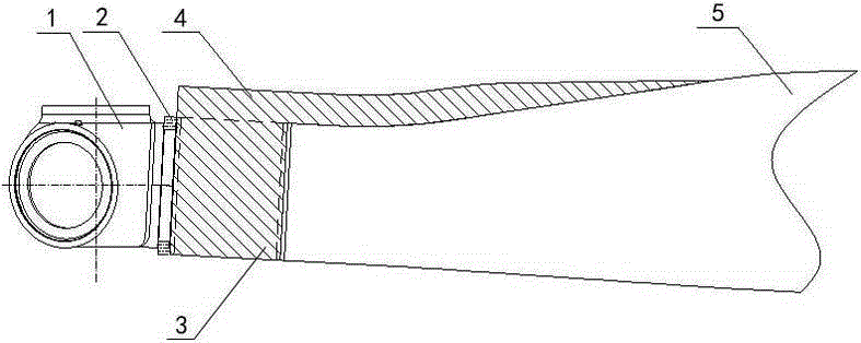
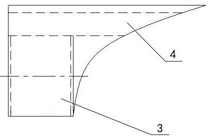
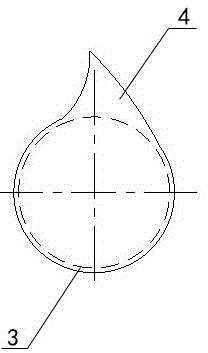
[0032] see figure 1 , figure 2 and image 3 : the wind wheel adjustment device 3 of the present invention is a hollow structure with an airfoil, which is in the shape of a blade segment. It is casted with non-metallic materials (of course, it can also be metal materials according to the requirements of use), and its two ends have inwardly folded flanges. The angle between the axis of the blade on the original hub and the vertical line of the axis of the main shaft of the fan) is defined as coaxial (that is, the angle between the axes of the flanges at both ends is 0) or inclined (that is, the axes of the flanges at both ends are at a certain angle) The included angle, usually the value of this included angle is in the range of 0-2° and cannot be 0, for example, 0.5°, 1°, 1.5° or 2°, etc.), to ensure the final size of the wind rotor (that is, sweep area) increases, the clearance distance between the tip of the blade and the tower is within a safe range. It is required that...
Embodiment 2
[0038] see Figure 4 , Figure 5 and Figure 6 : the wind wheel adjustment device 3 of the present invention is a hollow structure with an airfoil, which is in the shape of a blade segment. It is formed by casting non-metallic materials (of course, it can also be metal materials according to the requirements of use), and of course it can also be formed by split welding combination. The two ends of the adjustment device 3 have flanges folded inward respectively, and the flanges at both ends depend on the cone angle of the wind turbine of the wind turbine originally put into operation (that is, the angle between the axis of the blade on the original hub and the perpendicular to the axis of the main shaft of the fan), Coaxial (that is, the angle between the axes of the flanges at both ends is 0) or inclined (that is, different axes, the axes of the flanges at both ends form a certain angle, usually the value of this angle is in the range of 0 to 2° and When it cannot be 0, for...
Embodiment 3
[0045] see Figure 7 , the other structure of this embodiment is the same as that of Embodiment 2, the difference is that the positions of the pitch bearing 2 and the adjustment device 3 are adjusted relative to the hub 1, that is, the adjustment device 3 is directly connected to the hub 1 through several bolts Above, the outer ring of the pitch bearing 2 is connected to the adjustment device 3 by several bolts, and the blade 5 is connected to the inner ring of the pitch bearing 2 by several bolts. This connection structure makes the adjusting device 3 formed with one end corresponding to the flange of the hub 1 of the wind power generating set, and the other end corresponding to the flange of the pitch bearing 2 of the wind generating set. This assembly structure not only has the advantages of Embodiment 2, but also effectively reduces the load on the pitch bearing 2, which is conducive to reducing the strength requirements for the pitch bearing 2, improves the operating cond...
PUM
 Abstract
Description
Claims
Application Information
 - R&D
- Intellectual Property
- Life Sciences
- Materials
- Tech Scout
- Unparalleled Data Quality
- Higher Quality Content
- 60% Fewer Hallucinations
Browse by: Latest US Patents, China's latest patents, Technical Efficacy Thesaurus, Application Domain, Technology Topic, Popular Technical Reports.
© 2025 PatSnap. All rights reserved.Legal|Privacy policy|Modern Slavery Act Transparency Statement|Sitemap|About US| Contact US: help@patsnap.com


