
Rising swing blade type vertical-shaft wind generating set

A technology of wind turbines and vertical shafts, which is applied to wind motor combinations, wind engines, and wind engines at right angles to the wind direction, etc. It can solve the problems of difficult use, low service life, and low speed of wind rotors, and achieve strong wind resistance Good, the effect of preventing excessive power and preventing excessive speed

Inactive Publication Date: 2014-04-23
SHENZHEN BL E SCENERY THERMAL ENERGY TECH
View PDF5 Cites 2 Cited by
  • Summary
  • Abstract
  • Description
  • Claims
  • Application Information

AI Technical Summary

Problems solved by technology

In the prior art, the wind energy utilization rate of the vertical-axis lift fan can be as high as 42% during normal operation, but it has the following defects: small starting torque, complex structure, high cost, low speed of the wind rotor, poor stability, vibration, etc. Large and resonant, and a small range of wind speeds for effective use
However, the stability and balance of the vertical flexible wind rotor of the vertical axis flexible wind rotor also need to be further improved, and the resonance that is easy to occur in a wide speed range under the action of various wind forces and wind directions is relatively severe, which also It needs to be further solved, and the flexible suspension cable is easy to knot and break, which makes it have a low service life and is difficult to use in strong winds

Method used

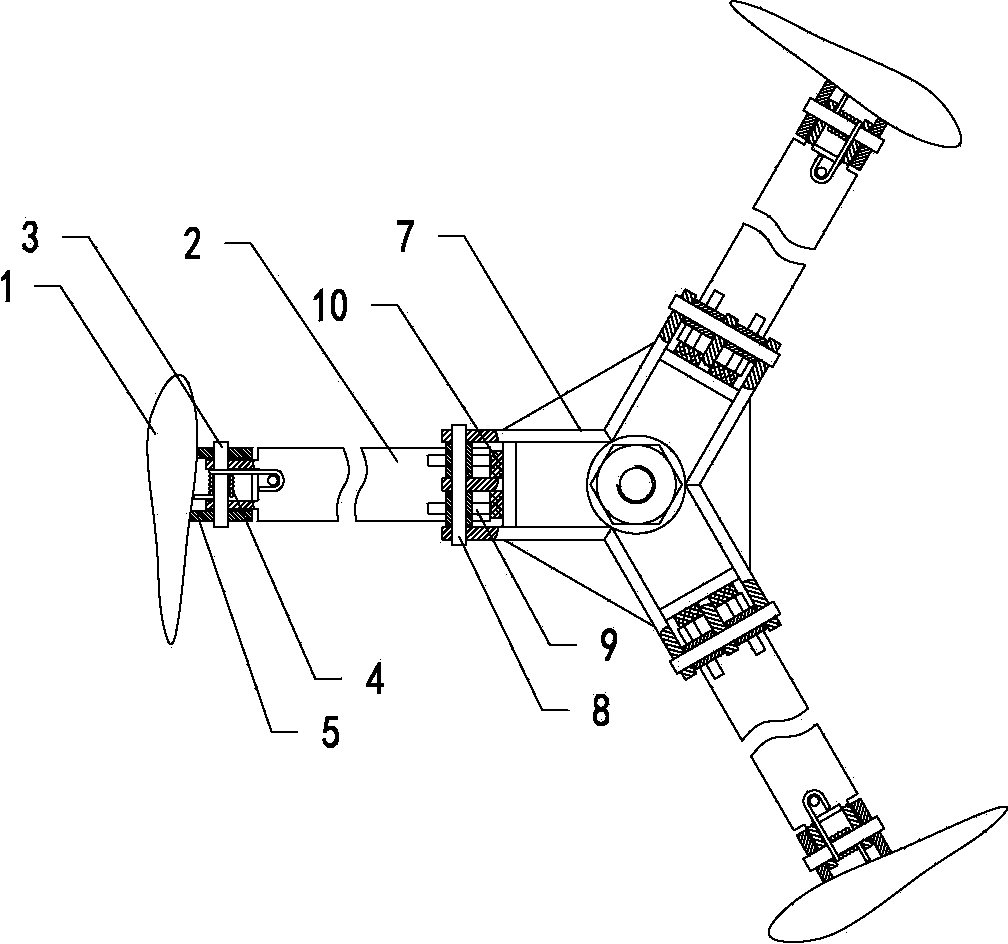
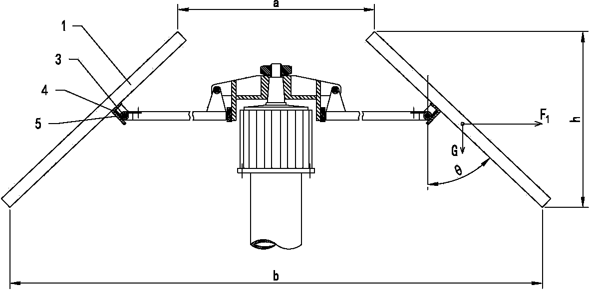
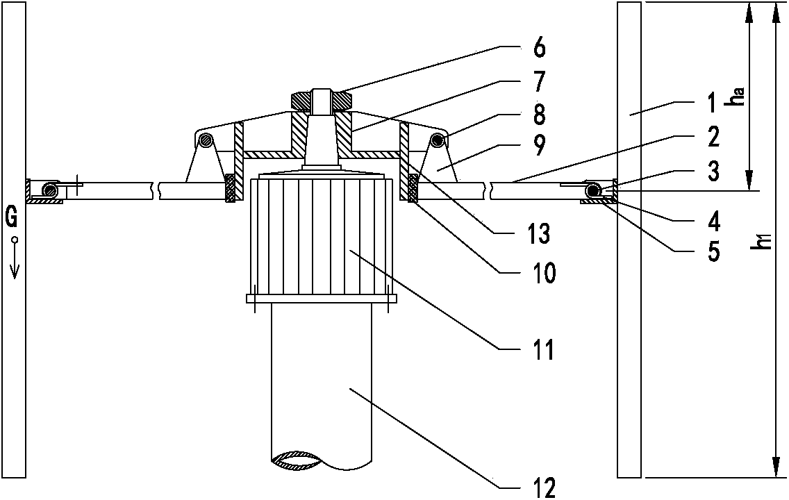

Image

  • Rising swing blade type vertical-shaft wind generating set
  • Rising swing blade type vertical-shaft wind generating set
  • Rising swing blade type vertical-shaft wind generating set

Examples


Embodiment 1

[0044] A wing-swinging-blade vertical-axis wind power generating set of the present invention, such as Figure 1 to Figure 3 As shown, it includes a generator 11 installed on the tower column 12 and a wind wheel installed on the vertical axis of the generator 11. The wind wheel includes a rotating bracket 7 and a plurality of sets of fan blade units. The rotating bracket 7 and the generator 11 The vertical axis is fixedly assembled and connected. Each group of fan blades 1 unit includes a support rod 2, a hinge mechanism and a fan blade 1. One end of the support rod 2 is provided with a hinged seat 9, which is hinged with the rotating bracket 7 through the first pin shaft 8. , the fan blade 1 is hinged to the other end of the strut 2 through a hinge mechanism, and when the wind wheel is stationary, all the struts 2 are at the same level. Wherein, the axial direction of the first pin shaft 8 is perpendicular to the length direction of the corresponding strut 2 , so that the bla...

Embodiment 2

[0066] A wing-swinging-blade vertical-axis wind power generating unit of the present invention is basically the same as Embodiment 2. In this embodiment, the five hinges are fixedly arranged on the groove-shaped hinges of the wind blade 1, and the two side walls A through hole for passing through the second pin shaft 3 is opened symmetrically, and the axis direction of the through hole is perpendicular to the length direction of the fan blade 1 . At the same time, one end of the support rod 2 hinged with the hinge 5 is provided with a hinge joint, and the hinge joint is provided with a through hole for passing through the second pin shaft 3, and the axis direction of the through hole is perpendicular to the length direction of the fan blade 1. And the hinge is located in the groove of the hinge 5, and the second pin 3 passes through the through hole of the hinge 5 and the through hole of the hinge. The second end of the hinge 5 is hinged to the strut 2 through the second pin 3...

Embodiment 3

[0069] A wing-swinging-blade vertical axis wind power generating unit of the present invention is basically the same as Embodiment 2. In this embodiment, the number of blade units is set to two groups, and the included angle between the two groups of blade units is 180°. °, the wind wheel of this structure has few materials, light weight and low cost.

[0070] The main technical solutions of this embodiment are basically the same as those of Embodiment 1 or Embodiment 2, and the features not explained in this embodiment are explained in Embodiment 1 or Embodiment 2, and will not be repeated here.


PUM


Abstract

The invention provides a rising swing blade type vertical-shaft wind generating set, wherein a hinged seat is arranged at one ends of support rods; the hinged seat is hinged to a rotating support through a first pin shaft and the axial direction of the first pin shaft is perpendicular to the length direction of the support rods; fan blades are hinged to the other ends of the support rods through a hinged mechanism; a buffer cushion is arranged between the rotating support and the support rods. Compared with the prior art, the support rods are hinged to the rotating support through the hinged seat and the first pin shaft, the stability of the vertical-shaft wind generating set is improved by virtue of the gyroscopic effect, and in the meantime, the buffer cushion made of an elastic material is arranged between the rotating support and the support rods of the rising swing blade type vertical-shaft wind generating set; the buffer cushion causes all the support rods to be located within the same horizontal plane, and as a result, the stability of the whole set is effectively guaranteed and the output power of the generator is kept stable. In addition, as the fan blades are hinged to the support rods through the hinged mechanism, the windward area of a wind wheel can be adjusted according to the wind power; the rising swing blade type vertical-shaft wind generating set is capable of generating power normally even at strong wind; the rising swing blade type vertical-shaft wind generating set is good in strong wind resistance, simple in structure without tail vane, material-saving and low in composite cost.

Description

technical field [0001] The invention relates to the technical field of vertical-axis wind power generators, in particular to a wing-swinging-blade vertical-axis wind power generator capable of stable rotation. Background technique [0002] At present, there are two main types of vertical-axis wind turbines. One is the lift-type wind turbine that uses the lift of the airfoil structure to do work. Its prototype is the Darrieus wind turbine. The manufacturing technology of most vertical-axis wind turbines is in On the basis of the operation principle of the airfoil structure, a little improvement technology is carried out; the other type is the resistance fan, whose prototype is the evolution of the wind cup wind meter, and the principle is to use the resistance of the front and back sides of the fan blade to the wind when it rotates horizontally Bad to do work. In the prior art, the wind energy utilization rate of the vertical-axis lift fan can be as high as 42% during normal...

Claims


Application Information

Patent Timeline
IPC IPC(8): F03D9/00F03D3/06F03D7/06
CPCY02E10/74F03D3/06F03D7/06F05B2260/77
Inventor 丑帅军刘湘威黄耀
Owner SHENZHEN BL E SCENERY THERMAL ENERGY TECH
Learn More