Portable CT (computed tomography) scanning equipment, portable CT system and CT detection method
A CT scanning and portable technology, applied in the field of non-destructive testing, can solve the problems of inconvenient movement of the measured object, inconvenient movement, and CT testing equipment cannot provide reliable and effective on-site testing services, and achieve effective on-site CT testing services and solve huge problems. The effect of consumption
- Summary
- Abstract
- Description
- Claims
- Application Information
AI Technical Summary
Problems solved by technology
Method used
Image
Examples
no. 1 example
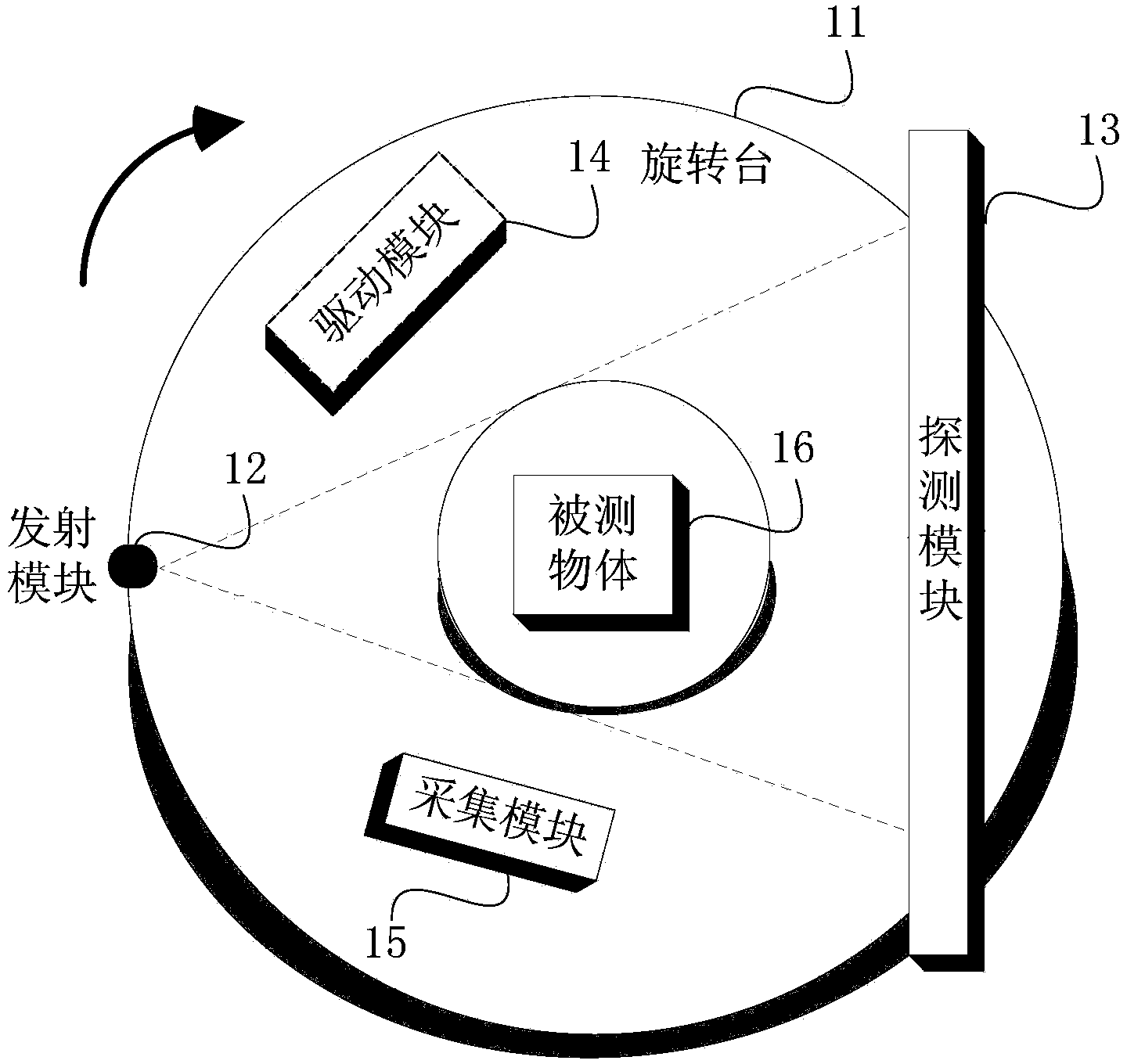
[0034] figure 1 It is a structural diagram of a portable CT scanning device according to the first embodiment of the present invention. Such as figure 1 As shown, the CT scanning device includes: a rotating table 11, an emission module 12 and a detecting module 13 arranged relatively on the rotating table 11, a driving module 14 arranged on the rotating table 11, and an acquisition module 15, wherein,
[0035] At least one of the transmitting module 12, the detecting module 13, the driving module 14 and the collecting module 15 is disassembled and assembled on the rotary table 11;
[0036] The driving module 14 is used to drive the transmitting module 12 and the detecting module 13 on the rotary table 11 to rotate synchronously;
[0037] Emitting module 12, used for emitting detection rays;
[0038] A detection module 13, configured to detect the detection ray, and convert the detection result into a digital signal;
[0039] The acquisition module 14 is configured to acqui...
no. 2 example
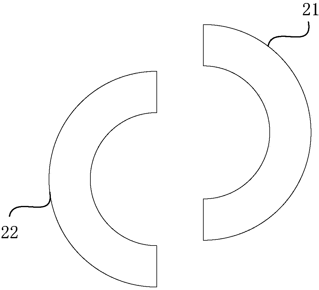
[0052] figure 2 It is a structural schematic diagram of a rotary table of a portable CT scanning device according to the second embodiment of the present invention. This embodiment is optimized on the basis of the above-mentioned embodiments. In this embodiment, the rotary table is preferably optimized as a multi-section spliced rotary table; and / or the rotary table is a hollow structure, and the hollow position is used to place the measured object.
[0053] Such as figure 2 As shown, the turntable of this embodiment is a ring-shaped hollow turntable, and its ring-shaped part is formed by splicing two sections. That is: the splicing component 21 and the splicing component 22, the combination of both can constitute a rotary table applied to various embodiments of the present invention. Of course, it can be understood that the rotating table can also adopt a three-stage splicing type or a four-stage splicing type, etc., which is not limited thereto.
[0054] In this embo...
no. 3 example
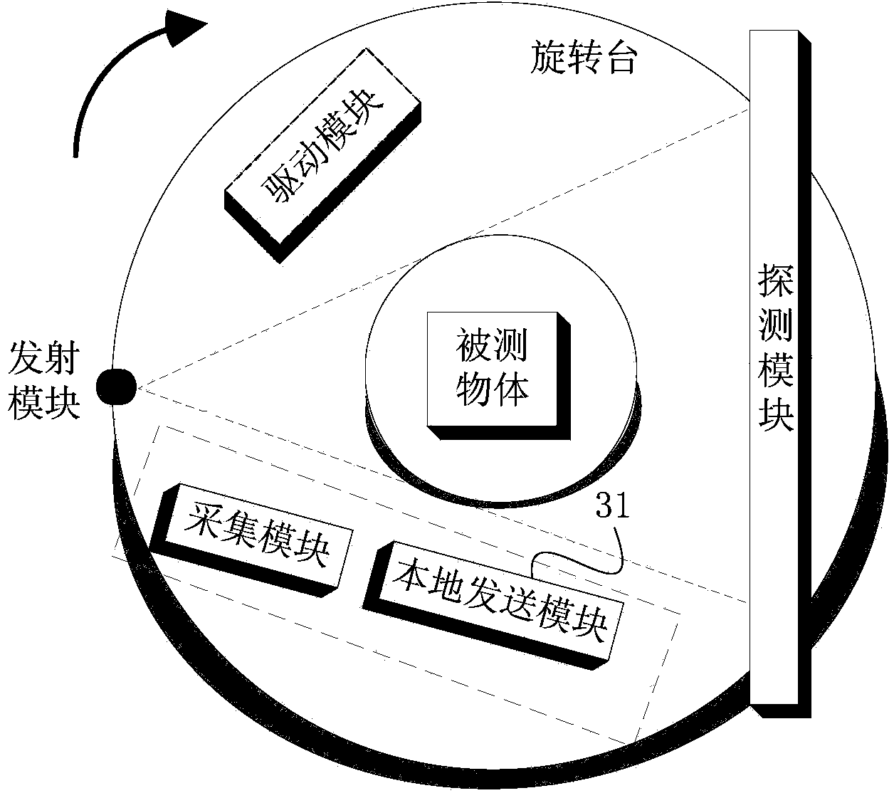
[0060] image 3 It is a structural diagram of a portable CT scanning device according to the third embodiment of the present invention. This embodiment is optimized on the basis of the above-mentioned embodiments. In this embodiment, it preferably further includes: a local sending module, which is used to wirelessly send the digital signal to realize remote processing of the digital signal and complete the CT image. reconstruction.
[0061] Such as image 3 As shown, the CT scanning system further includes: a local sending module 31, configured to wirelessly send the digital signal, so as to realize remote processing of the digital signal and complete CT image reconstruction.
[0062] Among them, in order to simplify the structure of the CT scanning device as much as possible, the acquisition module and the local sending module 31 can be integrated on the same circuit board or integrated in the same hardware module, and the circuit board or the hardware module can be indepen...
PUM
 Abstract
Description
Claims
Application Information
 - R&D
- Intellectual Property
- Life Sciences
- Materials
- Tech Scout
- Unparalleled Data Quality
- Higher Quality Content
- 60% Fewer Hallucinations
Browse by: Latest US Patents, China's latest patents, Technical Efficacy Thesaurus, Application Domain, Technology Topic, Popular Technical Reports.
© 2025 PatSnap. All rights reserved.Legal|Privacy policy|Modern Slavery Act Transparency Statement|Sitemap|About US| Contact US: help@patsnap.com


