
Method and device for directly controlling power of PWM rectifier under imbalanced network voltages

A grid voltage and power control technology, applied to harmonic reduction devices, reducing/preventing power oscillation, AC network to reduce harmonics/ripple, etc., can solve problems such as complex calculations

Inactive Publication Date: 2014-08-27
NORTH CHINA UNIVERSITY OF TECHNOLOGY
View PDF4 Cites 3 Cited by
  • Summary
  • Abstract
  • Description
  • Claims
  • Application Information

AI Technical Summary

Problems solved by technology

This scheme is easy to integrate into the existing DPC. Its disadvantage is that the acquisition of power compensation value needs to decompose the positive and negative sequences of the grid voltage and current and coordinate rotation transformation, and the calculation is relatively complicated.
[0004] At present, the direct power control based on the unbalanced grid voltage cannot meet the following requirements: 1) no need to extract positive and negative sequence components; 2) no need to calculate the power compensation value

Method used


Image

  • Method and device for directly controlling power of PWM rectifier under imbalanced network voltages
  • Method and device for directly controlling power of PWM rectifier under imbalanced network voltages
  • Method and device for directly controlling power of PWM rectifier under imbalanced network voltages

Examples


Embodiment approach

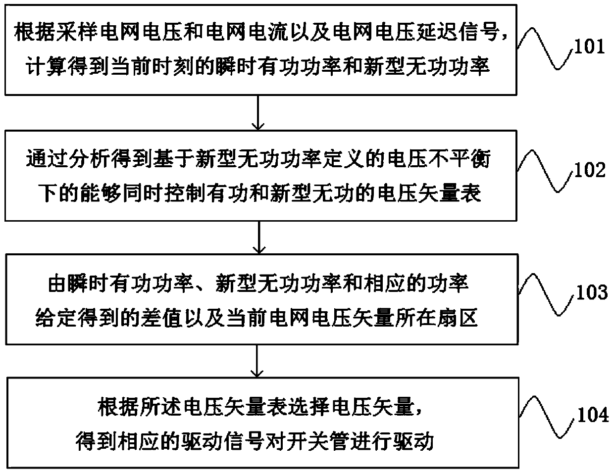
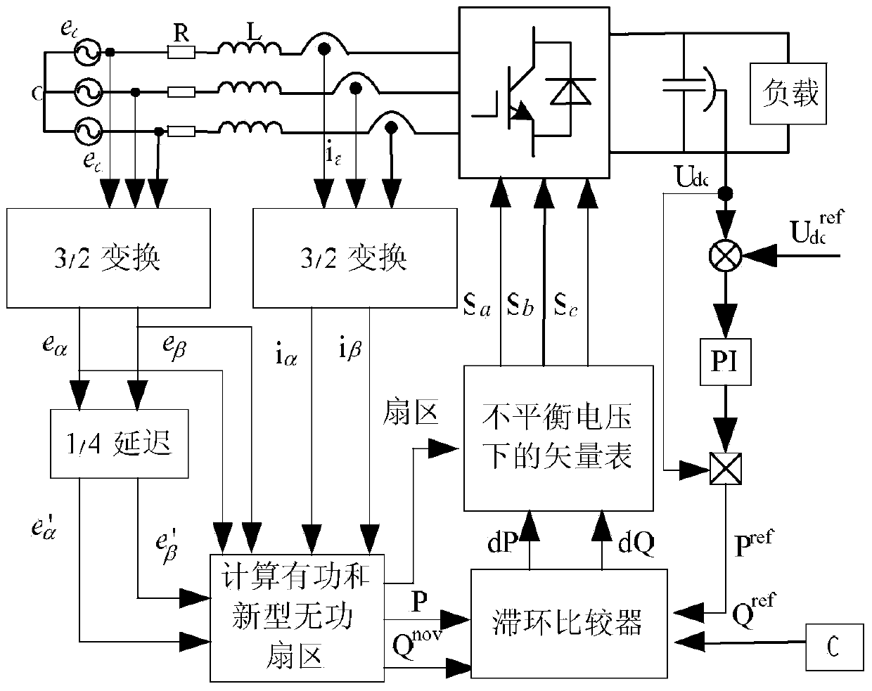
[0057] The direct power control method of the PWM rectifier under the unbalanced grid voltage based on the new definition of reactive power also includes another implementation, the steps of which include:

[0058] The voltage on the grid side is transformed by 3 / 2 to obtain the voltage signal e on the static two-phase αβ coordinates α , e β and the current signal i α , i β ; Further obtain the grid side voltage delay signal e through the 1 / 4 cycle delay function α ',e β ′; rectifier AC side voltage signal ν α , ν β Calculated by the voltage vector at the previous moment and the DC side voltage;

[0059] According to the grid-side voltage and grid-side current signals and the delay signal of the grid-side voltage obtained in the above steps, the instantaneous value of active power and new reactive power at the current moment can be obtained by analytical calculation;

[0060] Calculate the rate of change of active power and the rate of change of new reactive power under...


PUM


Abstract

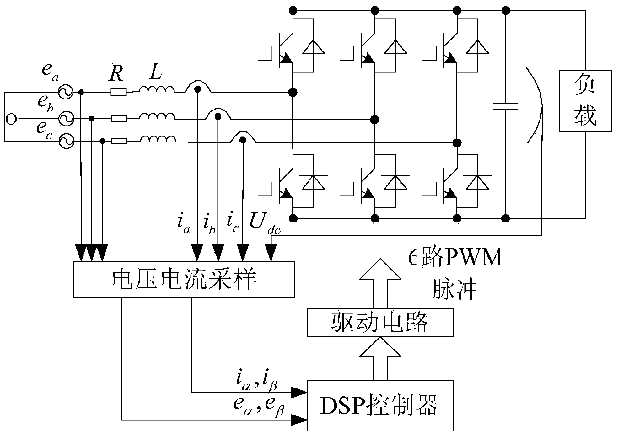
The invention discloses a method for directly controlling the power of a PWM rectifier under imbalanced network voltages. The method includes the steps that according to sampled network voltages, sampled network currents and network voltage delay signals, the instantaneous active power and the novel reactive power at the current moment are acquired through calculation; a voltage vector table capable of simultaneously controlling the active power and the novel reactive power based on voltage imbalance defined by the novel reactive power is acquired through analysis; an acquired difference value and a sector where a current network voltage vector is located are given through the instantaneous active power, the novel reactive power and the corresponding power; according to the voltage vector table, voltage vectors are selected, and corresponding driving signals are acquired for driving a switching tube. The invention further discloses a device for directly controlling the power adopting the method for directly controlling the power of the PWM rectifier. According to the method and device for directly controlling the power of the PWM rectifier, conversion of rotational coordinates is not needed, the calculated amount is small, implementation is easy, and robustness is good.

Description

technical field [0001] The invention relates to the technical field of power electronics, in particular to a method and device for direct power control of a PWM rectifier under unbalanced grid voltage. Background technique [0002] Direct power control is widely accepted because of its advantages of simple algorithm and fast dynamic response without coordinate rotation transformation. The direct power control has been deeply studied in the ideal grid, but in the actual grid, the grid voltage asymmetry will be caused by factors such as load imbalance and grid failure; if the traditional direct power control method is used, the grid side current will appear. A large number of harmonics, double-frequency fluctuations in the DC bus voltage and grid-side power, etc., seriously affect the performance of the system. For this reason, scholars from all over the world have done relevant research on direct power control under unbalanced grid conditions, in order to achieve constant DC...

Claims


Application Information

Patent Timeline
Patent Type & Authority Applications(China)
IPC IPC(8): H02J3/24H02J3/01
CPCY02E40/40
Inventor 张永昌曲昌琦
Owner NORTH CHINA UNIVERSITY OF TECHNOLOGY
Learn More