Low-cost separated component dimming circuit of LED light source

A technology of LED light source and dimming circuit, applied in the direction of light source, electric light source, electric lamp circuit layout, etc., can solve the problems of flicker, thyristor dimmer false triggering of LED lighting, etc., and achieve the effect of cost reduction

Inactive Publication Date: 2014-08-27
XIAMEN FIREFLY LED LIGHTING TECH
View PDF3 Cites 9 Cited by
  • Summary
  • Abstract
  • Description
  • Claims
  • Application Information

AI Technical Summary

Problems solved by technology

If these two currents cannot be met, false triggering of the thyristor dimmer and flickering of the LED lighting will occur

Method used


Image

  • Low-cost separated component dimming circuit of LED light source
  • Low-cost separated component dimming circuit of LED light source
  • Low-cost separated component dimming circuit of LED light source

Examples


Embodiment Construction

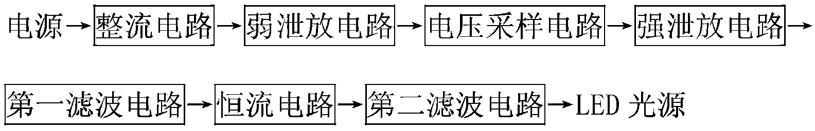
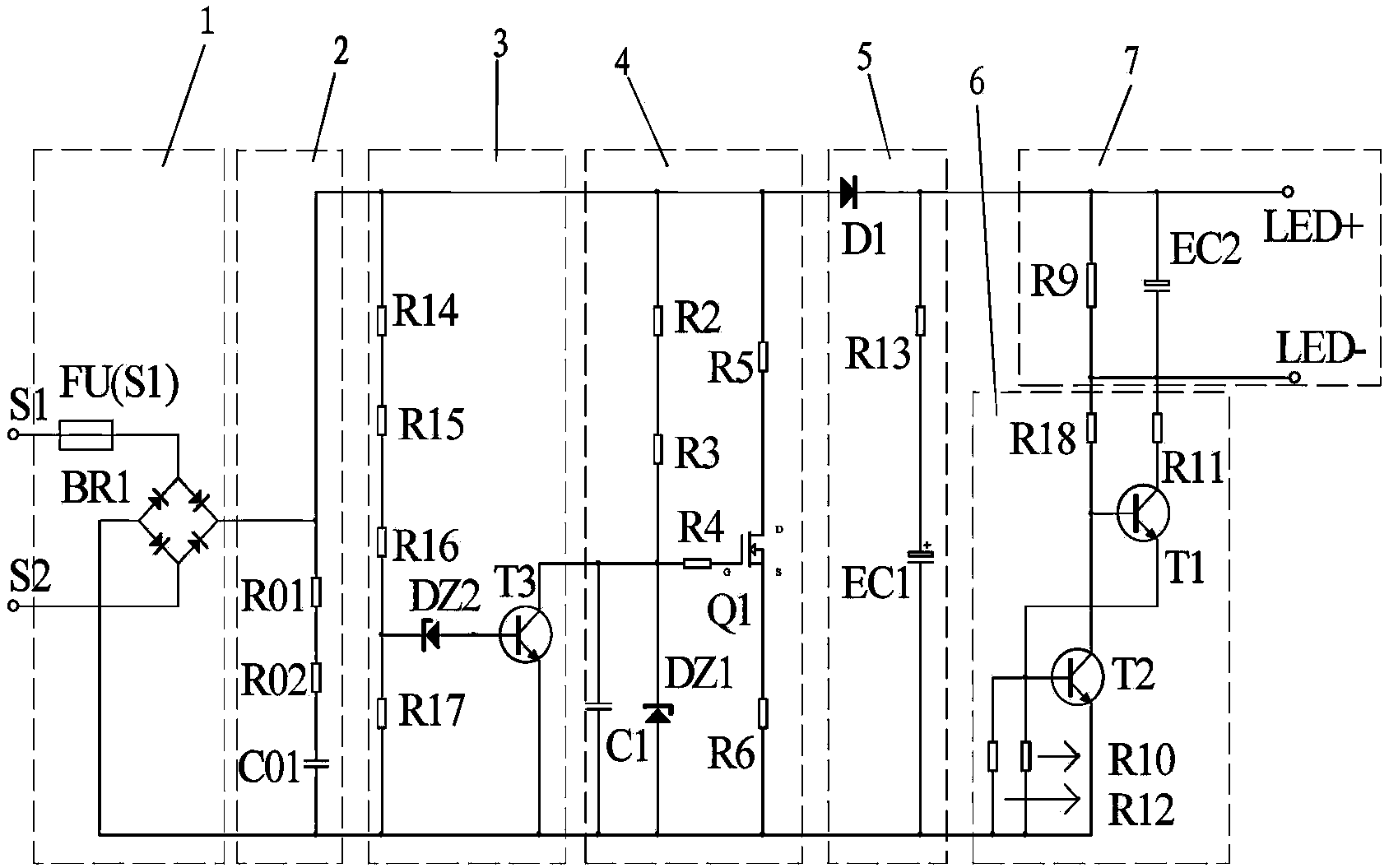
[0021] Such as figure 2 and image 3 , Figure 4 As shown, the dimming circuit of a low-cost discrete component LED light source disclosed by the present invention consists of a rectifier circuit 1, a weak discharge circuit 2, a voltage sampling circuit 3, a strong discharge circuit 4, and a first filter circuit 5 , a constant current circuit 6 and a second filter circuit 7. The input end of the rectification circuit 1 is connected to the power supply, and the output end is connected to the input end of the weak discharge circuit 2 . The output terminal of the weak discharge circuit 2 is connected to the input terminal of the strong discharge circuit 4 via the voltage sampling circuit 3 . The output terminal of the strong discharge circuit 4 is connected to the input terminals of the constant current circuit 6 and the second filter circuit 7 through the first filter circuit 5 . The output end of the constant current circuit 6 is also connected to the input end of the seco...


PUM


Abstract

The invention discloses a low-cost separated component dimming circuit of an LED light source. The low-cost separated component dimming circuit of the LED light source is composed of a rectifying circuit, a weak leakage circuit, a voltage sampling circuit, a strong leakage circuit, a first filter circuit, a constant current circuit and a second filter circuit. The input end of the rectifying circuit is connected with a power source, and the output end of the rectifying circuit is connected with the input end of the weak leakage circuit. The output end of the weak leakage circuit is connected with the input end of the strong leakage circuit through the voltage sampling circuit, and the output end of the strong leakage circuit is connected with the input end of the constant current circuit and the input end of the second filter circuit through the first filter circuit. The output end of the constant current circuit is also connected with the input end of the second filter circuit, and the output end of the second filter circuit is connected to the LED light source. According to the low-cost separated component dimming circuit of the LED light source, simple separated components are used for achieving dimming compatible with controlled silicon, the unique leakage circuits are combined with the simple constant current circuit to achieve the purpose of being compatible with a dimmer, and the cost of the dimming circuit is lowered by 200%.

Description

technical field [0001] The invention relates to a dimming circuit of an LED light source with low-cost discrete components. Background technique [0002] In the prior art, the principle of a typical thyristor dimmer is as follows figure 1 As shown, when the AC input voltage is applied to both ends of the thyristor U1, since the RC charging circuit composed of R2, R, and C3 has a charging time, the voltage on the capacitor C3 starts to charge from 0V, and the thyristor U1 There is a DIAC (two-way trigger diode, generally about 30V) in series with the driving pole of the driver, so the thyristor U1 is reliably cut off. At this time, the voltage on the capacitor C3 rises slowly. When it rises to 30V, the DIAC is triggered and turned on, and the thyristor The driving pole of U1 is turned on, and the thyristor U1 is reliably turned on. At this time, the voltage across the thyristor U1 instantly becomes zero, and the capacitor C3 passes through R, and R2 discharges rapidly. When ...

Claims


Application Information

Patent Timeline
Patent Type & Authority Applications(China)
IPC IPC(8): H05B37/02
Inventor 何润林陈周来
Owner XIAMEN FIREFLY LED LIGHTING TECH
Why Eureka
Try Eureka