Humerus greater tuberosity locking plate

A large tubercle and steel plate technology, applied in the direction of outer plate, fixer, internal bone synthesis, etc., can solve the problems affecting patients' early functional rehabilitation exercise, high tension band steel wire fixation strength, and reduce the stability between fracture fragments, etc., to achieve fixation Good stability, low cost, improved safety and effectiveness

Inactive Publication Date: 2014-09-03
薛兆龙
View PDF11 Cites 7 Cited by
  • Summary
  • Abstract
  • Description
  • Claims
  • Application Information

AI Technical Summary

Problems solved by technology

[0003] At present, surgical treatment is the main treatment, and there are many choices of internal fixation, but there are always some deficiencies, which are mainly manifested in: screw fixation may lead to further comminution of fracture fragments, and the addition of washers during fixation increases the size of the acromion The possibility of lower impact; the tension band steel wire fixation strength is high, which may cause iatrogenic humeral surgical neck fracture; if the greater tuberosity fracture of humerus is comminuted, the anchor suture may further reduce the stability between the fracture fragments, and Braunstein's biomechanical test shows that the biomechanical stability of anchor suture fixation is much lower than that of the screw group and the tension band group, and the statistical difference is obvious, which is bound to affect the early functional rehabilitation of patients after surgery; Larger, with the possibility of damage to the axillary nerve

Method used


Image

  • Humerus greater tuberosity locking plate
  • Humerus greater tuberosity locking plate
  • Humerus greater tuberosity locking plate

Examples


Embodiment Construction

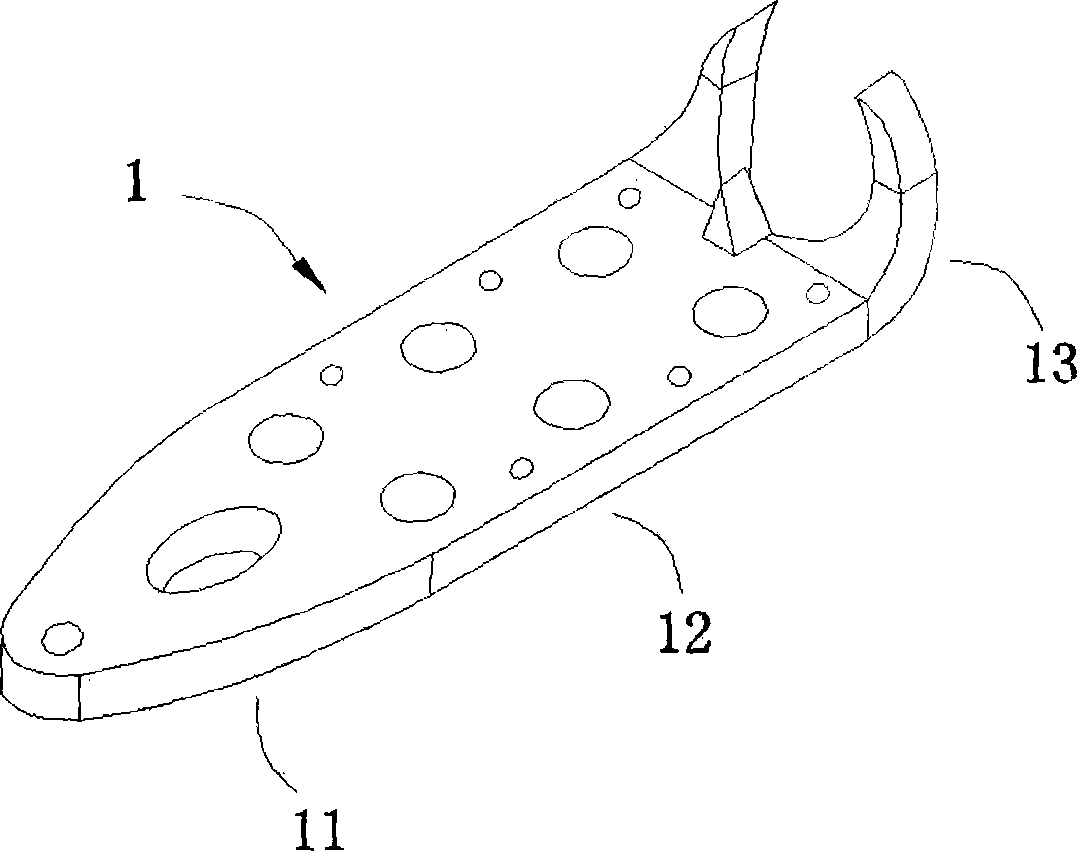
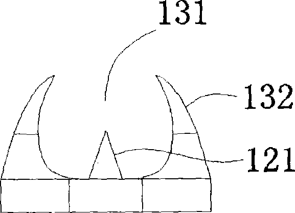
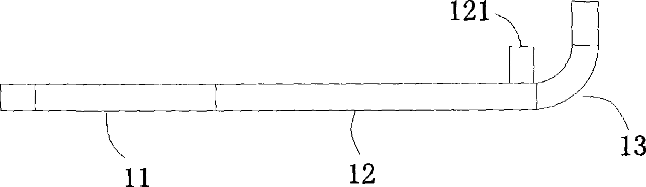
[0019] see Figure 1 to Figure 4 , a locking plate for the greater tuberosity of humerus provided in this embodiment, which includes a plate body 1, one end of the plate body 1 is tapered to form a fixed tail portion 11, the middle portion extends horizontally to form a fixed middle portion 12, and the other end faces to one side direction bending to form a fixed head 13, the middle part of the fixed head 13 is provided with a gap 131, so that a claw 132 is formed symmetrically on both sides, and the middle of the connection between the fixed middle part 12 and the fixed head 13 The position is provided with a protrusion 121, the fixed middle part 12 is provided with a plurality of locking screw holes 122 and Kirschner wire temporary fixing holes 123, and the fixed tail 11 is provided with a distal adjustment hole 111 and a distal Kirschner wire temporary Fixing hole 112 .

[0020] better, see figure 2 , the lower end of the claw 132 is relatively large, the upper end is be...


PUM


Abstract

The invention discloses a humerus greater tuberosity locking plate. The humerus greater tuberosity locking plate comprises a plate body. The plate body comprises a fixed head portion, a fixed middle portion and a fixed tail portion which are sequentially connected. Two clamping jaws are symmetrically arranged on the fixed head portion, a protrusion is arranged on the fixed middle portion, a plurality of locking screw holes and a plurality of kirschner wire temporary fixing holes are formed in the fixed middle portion, and a far-end adjusting hole and a far-end kirschner wire temporary fixing hole are formed in the fixed tail portion. The humerus greater tuberosity locking plate is reasonable in structural design, the tension band principle is applied, the patella fixing structure and the patellar tendon principle are used for reference, the clamping jaws and the protrusion are arranged ingeniously, the positions are arranged scientifically, the locking plate can be better anchored with and attached to a greater tuberosity fragment, the requirements that rotator cuff muscle activities are affected to the minimum and the fragment is firmly fixed to the maximum are met, the fixing stability is good, the safety and the effectiveness of operations are greatly improved, operation is convenient and flexible, trauma is small, and unnecessary pain is prevented from being brought to patients. In addition, the humerus greater tuberosity locking plate is simple in overall structure, low in cost, easy to realize and convenient to apply and popularize widely.

Description

technical field [0001] The invention relates to the technical field of fixation tools for treating fractures of the greater tuberosity of the humerus, in particular to a locking steel plate for the greater tuberosity of the humerus for treating fractures of the greater tuberosity of the humerus. Background technique [0002] The greater tuberosity fracture of the humerus is a part of the proximal humeral fracture, and it can also be a shoulder dislocation combined with a greater tuberosity fracture. It is a common clinical trauma, and comminuted fractures are common. Due to its anatomical characteristics, the impact of the poor position of the greater tuberosity of the humerus, in addition to the subacromial impingement sign, may also cause rotator cuff muscle dysfunction, which is directly related to the postoperative functional rehabilitation of the affected shoulder. [0003] At present, surgical treatment is the main treatment, and there are many choices of internal fixa...

Claims


Application Information

Patent Timeline
Patent Type & Authority Applications(China)
IPC IPC(8): A61B17/80
CPCA61B17/8009A61B17/8061A61B17/809
Inventor 薛兆龙
Owner 薛兆龙
Why Eureka
Try Eureka