Plasticized material receiving structure of injection blow molding machine

An injection blowing machine and injection molding technology, which is applied in the field of injection blowing machine plasticizing and receiving structure, can solve the problems of waste of resources, unstable movement, waste of energy, etc., and achieve the effects of improving work efficiency, reducing safety accidents, and saving human resources

Active Publication Date: 2014-09-03
张家港市联鑫塑料机械有限公司
View PDF4 Cites 3 Cited by
  • Summary
  • Abstract
  • Description
  • Claims
  • Application Information

AI Technical Summary

Problems solved by technology

However, the existing bottle blowing machines usually use hydraulic low-speed high-torque motors to realize the rotation of the plasticizing screw. During operation, the movement is very unstable and wastes energy; Placed on the conveyor belt, this increases labor costs and is prone to safety accidents; now there are injection molded parts made into movable parts, but during the use of this kind of moving parts, the sliding is not smooth enough, the amount of wear is large, and waste resource

Method used


Image

  • Plasticized material receiving structure of injection blow molding machine
  • Plasticized material receiving structure of injection blow molding machine
  • Plasticized material receiving structure of injection blow molding machine

Examples


Embodiment Construction

[0017] The present invention will be described in detail below in conjunction with the accompanying drawings.

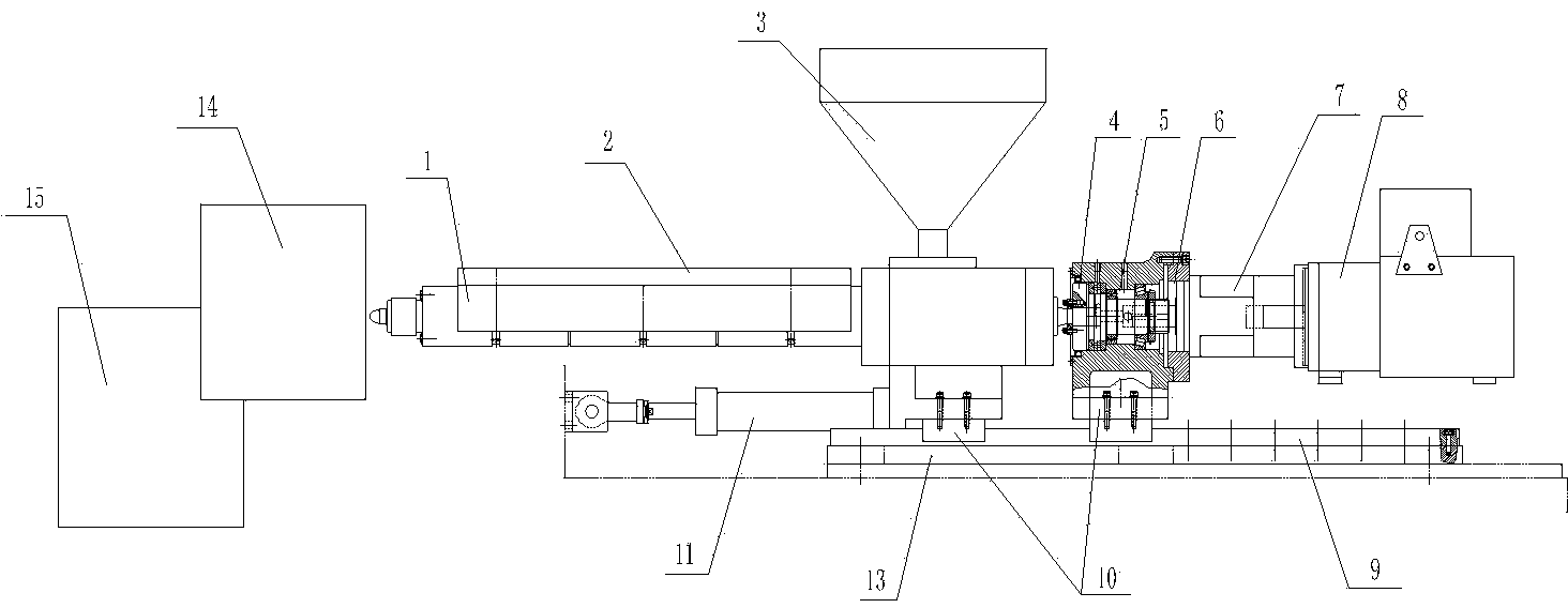
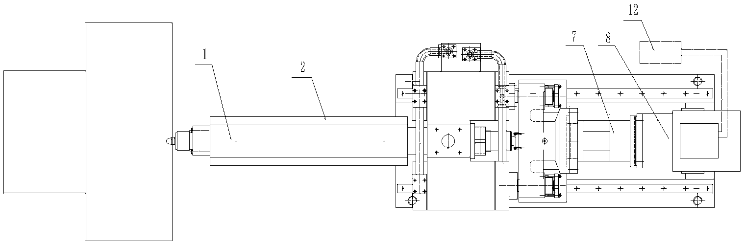
[0018] Such as Figure 1 ~ Figure 4 A kind of injection blowing machine plasticization receiving structure shown, comprises frame, is provided with injection molding part on described frame, and described injection molding part is provided with molding part 14, and described injection molding part comprises plasticizing screw rod 1. The outer casing 2 of the plasticizing screw 1 and the driving device for driving the plasticizing screw 1 to rotate. A moving device for the injection part is provided under the injection part, and a device for automatically transferring products is provided at the exit of the molding part 14. Rotary device 15.

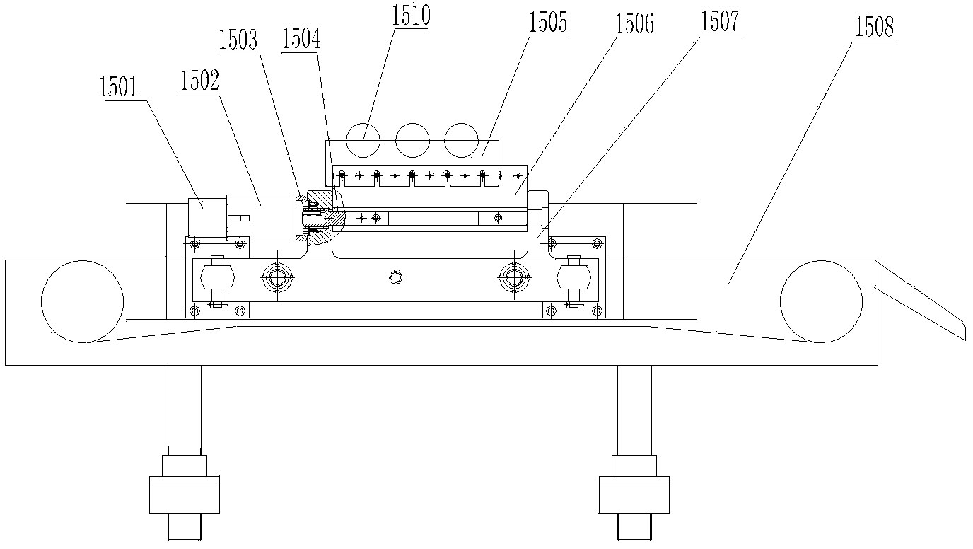
[0019] The rotating device includes a push hydraulic cylinder 1509 arranged on the frame of the injection blowing machine. A fixed mount 1507 is arranged on the head of the hydraulic cylinder shaft of the push hydraulic cylinde...


PUM


Abstract

The invention relates to a plasticized material receiving structure of an injection blow molding machine. The plasticized material receiving structure comprises a frame, wherein an injection molding part is arranged on the frame, a forming part is arranged beside the injection molding part, and the injection molding part comprises a plasticized screw rod, a housing arranged outside the plasticized screw rod, and a driving device used for driving the plasticized screw rod to rotate; a moving device for driving the injection molding part to move is arranged below the injection molding part, and a rotating device used for automatically transferring products is arranged in an outlet of the forming part. By adopting the structure, the improved driving device and a servo motor are used, so that the plasticized position can be smoothly fed; the moving device is adopted, so that the plasticized position can be smoothly pushed; the rotating device is adopted, so that the automatic feed of the machine can be guaranteed so as to enable the automation to be realized, the working efficiency can be improved, manpower resources are saved, the abrasion is reduced, and safety accidents are reduced.

Description

technical field [0001] The invention relates to an injection molding equipment in the injection molding technology, in particular to a plasticized material receiving structure of an injection blowing machine. Background technique [0002] Injection blow molding machine is a kind of equipment that makes plastic particles into hollow containers through blow molding process. At present, the more common models include hollow extrusion blow machines that use PP and PE for one-time molding, and use PET, PC or PP for two-time molding. Advanced injection stretch blow molding machines, as well as the newly developed multi-layer hollow extrusion blow molding and stretch blow molding. However, the existing blow molding machines usually use hydraulic low-speed high-torque motors to realize the rotation of the plasticizing screw. During operation, the movement is very unstable and wastes energy; when collecting products, workers need to collect and collect them manually Placed on the co...

Claims


Application Information

Patent Timeline
Patent Type & Authority Applications(China)
IPC IPC(8): B29C49/06B29C49/28B29C49/42
Inventor 何志斌倪爱明任巧安
Owner 张家港市联鑫塑料机械有限公司
Why Eureka
Try Eureka