
Lateral current collector with double four-bar mechanisms connected in series

A technology of four-bar linkage mechanism and lateral flow receiving, which is applied in the field of current collectors, can solve problems such as jumping and arcing of the current receiving shoe, adapt to small expansion and contraction range, and unstable current receiving of trains, etc., so as to achieve reliable current receiving High performance, large stretch, flexible structure and layout

Active Publication Date: 2014-09-03
湖南星光速流科技有限责任公司
View PDF6 Cites 22 Cited by
  • Summary
  • Abstract
  • Description
  • Claims
  • Application Information

AI Technical Summary

Problems solved by technology

[0003] Among the existing current collectors, a typical current collector (a lateral current collector, patent number ZL201010557003.7) uses a single quadrilateral structure to realize the telescopic action of the sliding shoe. The disadvantage is that the structural layout is flexible. Low performance, unable to adapt to the system coordination requirements of the spatial structure layout under the large expansion and contraction size, adapt to the small expansion and expansion range, when the train has a large lateral displacement and deflection relative to the track, it is easy to cause the flow-absorbing shoe to jump and arc. It makes the train unsteady when receiving current, and the single quadrilateral structure is not suitable for the application under the working conditions requiring large stretching range

Method used


Image

  • Lateral current collector with double four-bar mechanisms connected in series
  • Lateral current collector with double four-bar mechanisms connected in series
  • Lateral current collector with double four-bar mechanisms connected in series

Examples


Embodiment 1

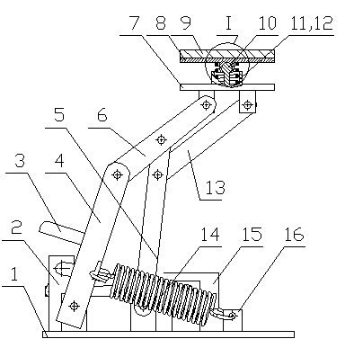
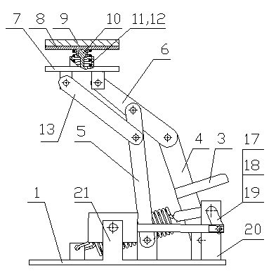
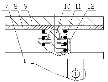
[0044] It is mainly composed of a base 1, a drive locking mechanism 2, a flow-collecting shoe 9, a shoe seat 7 and a swing mechanism. The swing mechanism is connected between the base 1 and the shoe seat 7, the driving locking mechanism 2 is installed between the base 1 and the bottom of the swing mechanism, and the flow collector shoe 9 is installed on the side of the shoe seat 7 facing away from the swing mechanism . The swing mechanism is composed of the bottom four-bar linkage mechanism and the top four-bar linkage mechanism connected in series: the bottom four-bar linkage mechanism is composed of the base 1, the main swing rod 4, the lower half of the upper support rod 6 and the lower link 5; The rod mechanism is composed of the upper half of the upper support rod 6, the shoe seat 7, the upper connecting rod 13 and the upper half of the lower connecting rod 5; three hinged holes are respectively set on the lower connecting rod 5 and the upper supporting rod 6 to form The...

Embodiment 2

[0046] It is basically the same as Embodiment 1, the difference is that the ball joint limit seat 12 is set outside the return spring 11, and the ball joint limit seat 12 and the fixed shaft of the ball joint 10 are installed on the sliding shoe seat 7 or the sliding shoe is installed at the same time. plate 8.

Embodiment 3、4

[0048] It is basically the same as Embodiments 1 and 2, but the difference is the structure of the driving locking mechanism 2: the driving locking mechanism 2 mainly includes a tension spring 14, a cylinder 15, a tension spring fixed support 16, a driving lever 3, and a bell crank , bellcrank support 20 and cylinder support 21; bellcrank support 20 and cylinder support 21 are all installed on the base 1; bellcrank is composed of driving wing plate 17, bellcrank rotating shaft 18 and stirring wing plate 19 to form rigid structure , installed on the bell crank support 20 through the crank crank shaft 18, the crank crank shaft 18 and the central axis of the toggle wing plate 19 form an included angle of 20-50 degrees; the cylinder 15 is hinged with the cylinder support 21; the drive wing plate 17 is hingedly connected with the main shaft of the cylinder 15, and the toggle wing 19 is adjacent to the main fork 4, and the driving lever 3 is installed on the main fork 4 above the tog...


PUM


Abstract

The invention discloses a lateral current collector with double four-bar mechanisms connected in series. The lateral current collector comprises a base, a drive locking mechanism, a current collection sliding shoe, a sliding shoe base and a swing mechanism. The swing mechanism is connected between the base and the sliding shoe base. The drive locking mechanism is installed between the base and the bottom of the swing mechanism. The current collection sliding shoe is installed on the side, back on to the swing mechanism, of the sliding shoe base. The swing mechanism is formed by connecting the top four-bar mechanism and the bottom four-bar mechanism in series. The bottom four-bar mechanism is composed of a base, a main swing bar, the lower half part of an upper supporting bar and a lower connecting bar. The top four-bar mechanism is composed of the upper half part of the upper supporting bar, the sliding shoe base, an upper connecting bar and the upper half part of the lower connecting bar. A sliding shoe installation plate is arranged between the sliding shoe base and the current collection sliding shoe and connected with the sliding shoe base through a spherical hinge or a double-shaft deflection mechanism. The lateral current collector is simple and reasonable in structure and large in extension amplitude, and the current collection reliability of the lateral current collector can be guaranteed even when the lateral displacement and deflection amplitude of a train are large.

Description

technical field [0001] The invention relates to a current collector, in particular to a lateral current collector with a double four-bar linkage mechanism in series, which is suitable for use on the lines of monorail trains and conventional maglev trains in the elevated line traffic mode. Background technique [0002] The current collector is a current receiving device installed on the frame of the urban rail transit vehicle. Through the sliding contact between the sliding shoes on the current collector and the ground power supply rail, the ground electric energy is guided to the train. When the current receiver is working normally, under the action of the spring force, the current receiver swing rod and the current receiver sliding shoe are pressed to the power supply rail (the third rail), so that the current receiver sliding shoe is in contact with the power supply rail. [0003] Among the existing current collectors, a typical current collector (a lateral current collect...

Claims


Application Information

Patent Timeline
IPC IPC(8): B60L5/39
Inventor 陈革陈俊铭
Owner 湖南星光速流科技有限责任公司
Learn More