
A transmission structure of LTCC substrate microwave signal and its manufacturing method

A microwave signal and transmission structure technology, applied in the direction of waveguides, waveguide-type devices, circuits, etc., can solve the problems of uneven shrinkage, surface through-hole bulges, affecting the assembly of chips and components, and achieve flexible structural layout. Isolation, easy-to-achieve effects

Active Publication Date: 2020-03-27
SOUTHWEST CHINA RES INST OF ELECTRONICS EQUIP
View PDF4 Cites 0 Cited by
  • Summary
  • Abstract
  • Description
  • Claims
  • Application Information

AI Technical Summary

Problems solved by technology

[0003] The microwave signal transmission channels in the LTCC substrate usually use high-density metallized stacked through-hole grounding to achieve electromagnetic isolation, but the isolation is usually below 40dB, especially not well suited to the miniaturization of high-frequency bands and high-performance substrates Integration requirements
And the introduction of local high-density stacked through holes is likely to lead to the following problems: 1) lead to uneven shrinkage, warping or plane distortion of the substrate, 2) stacked holes cause surface through holes to protrude, affecting the assembly of chips and components
[0004] Most of the current research on the transmission performance of LTCC substrates focuses on the design and implementation of microwave devices, and there is no implementation method for high isolation between LTCC microwave signal transmission channels in the prior art

Method used


Image

  • A transmission structure of LTCC substrate microwave signal and its manufacturing method
  • A transmission structure of LTCC substrate microwave signal and its manufacturing method
  • A transmission structure of LTCC substrate microwave signal and its manufacturing method

Examples


Embodiment Construction

[0029] All the features disclosed in this specification, or all disclosed methods or steps in the process, except for mutually exclusive features and / or steps, can be combined in any manner.

[0030] Any feature disclosed in this specification, unless specifically stated, can be replaced by other equivalent or equivalent alternative features. That is, unless otherwise stated, each feature is just one example of a series of equivalent or similar features.

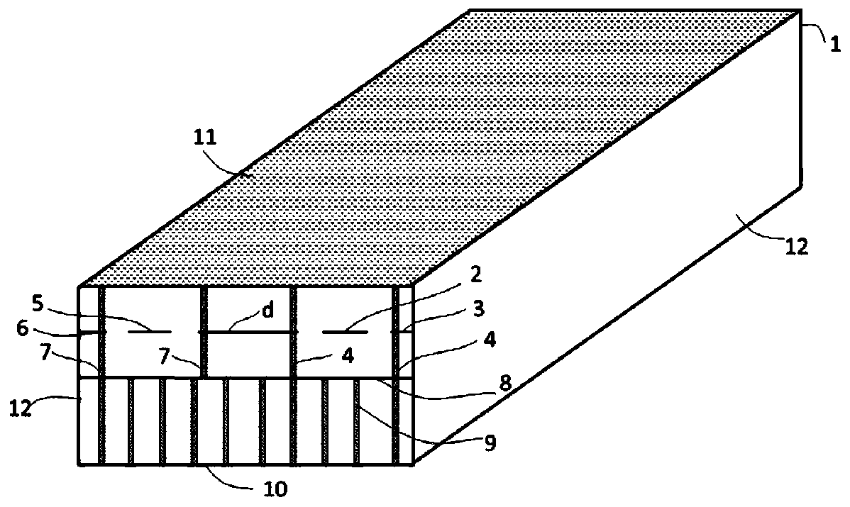
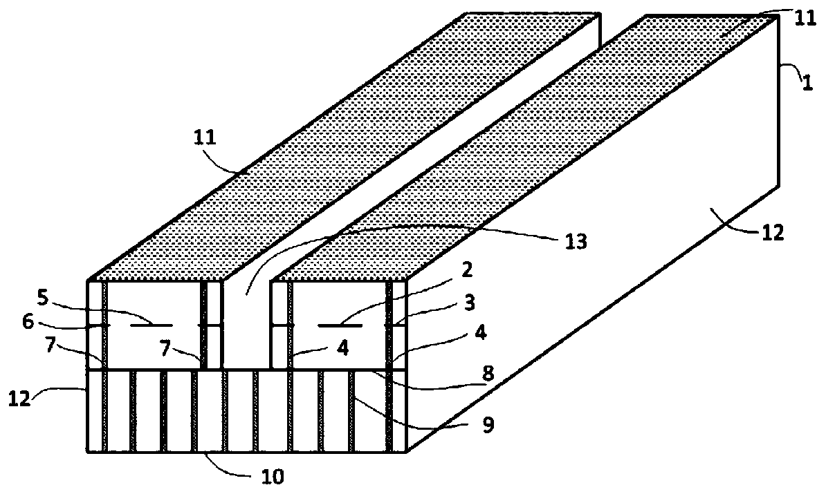
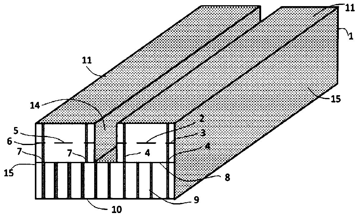
[0031] In order to achieve the purpose of the present invention, the present invention provides a microwave signal transmission structure of an LTCC substrate and a manufacturing method thereof. The transmission structure includes a microwave signal transmission channel and an isolation cavity. The microwave signal transmission channel includes a signal transmission line and a microwave ground. And a ground hole, the isolation cavity slot is between the microwave signal transmission channels that need to be isolated, and the side...


PUM

PropertyMeasurementUnit
widthaaaaaaaaaa
lengthaaaaaaaaaa
depthaaaaaaaaaa

Abstract

The present invention discloses an LTCC substrate microwave signal transmission structure and a manufacturing method thereof. The transmission structure comprises microwave signal transmission channels and an isolation cavity groove, each microwave signal transmission channel comprises one signal transmission line, one microwave stratum and one ground hole, the isolation cavity groove is arrangedbetween the microwave signal transmission channels required being isolated, and the side wall of the cavity groove is coated with a metal film layer. The manufacturing method comprises the steps of: manufacturing the microwave signal transmission channels, manufacturing cavity grooves at an area requiring achieving electromagnetic isolation on a LTCC substrate, and finally, performing metallization of the side wall of the cavity groove to achieve the electromagnetic isolation of the microwave signals at two sides of the cavity groove, wherein the isolation area is an area requiring electromagnetic isolation between the microwave signal transmission channels. The LTCC substrate microwave signal transmission structure and the manufacturing method thereof can achieve high isolation between the microwave signal transmission channels in the substrate so as to improve the electromagnetic compatibility of the internal portion of the LTCC substrate.

Description

Technical field [0001] The present invention relates to the field of LTCC substrates, in particular to a transmission structure of LTCC substrate microwave signals and a manufacturing method thereof. Background technique [0002] With the continuous deepening of multi-function and miniaturization, more and more microwave devices or microwave signal transmission channels are integrated in LTCC substrates. 8 RF transmission channels are usually integrated in T / R component substrates. Frequency conversion components and switch matrices usually require Integrating more than 4 internal embedded filters. At the same time, the application frequency band of LTCC substrates is getting higher and higher, and the distance between microwave devices and microwave signal transmission channels is getting smaller and smaller. Electromagnetic isolation has become a substrate with miniaturization and high performance. An outstanding problem. [0003] The high-density metallization stack through-hol...

Claims


Application Information

Patent Timeline
Patent Type & Authority Patents(China)
IPC IPC(8): H01P3/00
CPCH01P3/00
Inventor 岳帅旗杨宇刘志辉张刚黄翠英
Owner SOUTHWEST CHINA RES INST OF ELECTRONICS EQUIP
Learn More