Robot walking leg mechanism with integration of wheel type, foot type and wheel-foot composite type

A composite and robotic technology, applied in the fields of motor vehicles, transportation and packaging, etc., can solve the problems that cannot be applied to legged robots and ground vehicles, etc., to improve the stability of the body, reduce the difficulty of control, and increase the wheel-ground contact area Effect

Active Publication Date: 2014-09-03
HARBIN INST OF TECH
View PDF6 Cites 9 Cited by
  • Summary
  • Abstract
  • Description
  • Claims
  • Application Information

AI Technical Summary

Problems solved by technology

[0004] The purpose of the present invention is to solve the problem that the legged walking part of the existing wheel-legged mechanism cannot be applied to legged robots and ground vehicles operating under mixed terrain conditions

Method used


Image

  • Robot walking leg mechanism with integration of wheel type, foot type and wheel-foot composite type
  • Robot walking leg mechanism with integration of wheel type, foot type and wheel-foot composite type

Examples


specific Embodiment approach 1

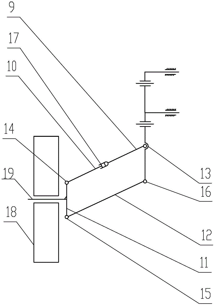
[0016] Embodiment 1: Combining Figure 1-Figure 2 Describing this embodiment, the walking leg mechanism of the robot that integrates wheeled, footed and wheeled-foot composite walking in this embodiment includes a front swing rod assembly, a side swing rod assembly, a wheel shaft 8, a wheel 18 and a connecting rod 2, which are connected to The rod 2 is arranged vertically, the front sway rod assembly is installed on the upper part of the connecting rod 2, one end of the side sway rod assembly is installed on the lower part of the connecting rod 2, and the side sway rod assembly is perpendicular to the front sway rod assembly, and the wheel axle 8 is connected to the side. The other end of the swing rod assembly is connected, and the wheel 18 is rotatably sleeved on the wheel axle 8,

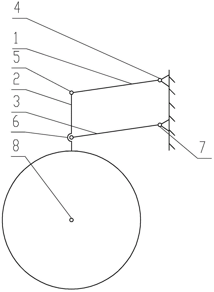
[0017] The front swing rod assembly includes a front swing first link 1 , a front swing third link 3 , a front swing first hinge 4 , a front swing second hinge 5 , a front swing third hinge 6 and...

specific Embodiment approach 2

[0019] Specific implementation mode 2: Combining Figure 1-Figure 2 Describing this embodiment, the lengths of the first front swing link 1 and the front swing third link 3 in this embodiment are equal, the front swing first hinge 4 , the front swing second hinge 5 , the front swing third hinge 6 and the front swing The axes of the fourth pendulum hinge 7 are parallel to each other, the front pendulum first link 1, the upper part of the connecting rod 2, the front pendulum third link 3, the vehicle body, the front pendulum first hinge 4, the front pendulum second hinge 5, the front pendulum The third hinge 6 of the pendulum and the fourth hinge 7 of the front swing constitute a parallel four-bar mechanism. This arrangement is convenient to realize the active swing in the front-rear direction of the present invention by driving the first front-swing hinge 4 or the fourth front-swing hinge 7 by the motor or hydraulic pressure on the robot. Other components and connection relati...

specific Embodiment approach 3

[0020] Specific implementation three: combination Figure 1-Figure 2 Describing the present embodiment, the distance between the side swing first hinge 13 and the side swing fourth hinge 16 in this embodiment is equal to the distance between the side swing second hinge 14 and the side swing third hinge 15 . The axes of the hinge 13, the second hinge 14 for the side swing, the third hinge 15 for the side swing and the fourth hinge 16 for the side swing are parallel to each other and perpendicular to the axis of the first hinge 4 for the front swing. Link 9, side swing second link 10, side swing third link 11, side swing fourth link 12, side swing first hinge 13, side swing second hinge 14, side swing third hinge 15 and side The fourth hinge 16 of the pendulum constitutes a planar four-bar mechanism. This arrangement facilitates the implementation of the lateral active swing of the present invention by driving the first side swing hinge 13 or the side swing fourth hinge 16 by t...


PUM


Abstract

The invention discloses a robot walking leg mechanism with integration of a wheel type, a foot type and a wheel-foot composite type and relates to a robot walking leg mechanism. The robot walking leg mechanism aims at solving the problem that a foot-type traveling part of an existing wheel-leg type mechanism can not be applied to a foot-type robot and a ground vehicle operating under the condition of mixed terrains. The robot walking leg mechanism comprises a front swinging rod component, a side swinging rod component, a wheel shaft (8), a wheel (18) and a connecting rod (2), wherein the connecting rod (2) is vertically arranged; the front swinging rod component is arranged at the upper part of the connecting rod (2); one end of the side swinging rod component is arranged at the lower part of the connecting rod (2); the side swinging rod component is vertical to the front swinging rod component; the wheel shaft (8) is connected with the other end of the side swinging rod component; the wheel (18) rotatably sheathes the wheel shaft (8). The robot walking leg mechanism disclosed by the invention is used on a robot.

Description

technical field [0001] The invention relates to a four-degree-of-freedom plane link-type robot walking leg mechanism, in particular to a robot walking leg mechanism integrating wheel-type, foot-type and wheel-foot compound walking functions. Background technique [0002] The walking leg is an important part of the footed walking robot, and the performance of the walking leg is directly related to the walking speed, efficiency, obstacle-surmounting ability, ditch-crossing ability and terrain adaptability of the robot. Compared with wheeled robots, footed robots have the disadvantages of slow walking speed and low driving efficiency. Energy utilization efficiency has become the most important factor limiting the payload weight ratio of footed robots; but at the same time, footed robots also have a strong ability to overcome obstacles. , the moving direction can be adjusted in all directions, the terrain adaptability is strong, and the movement flexibility is good. [0003] Th...

Claims


Application Information

Patent Timeline
IPC IPC(8): B62D57/028B62D57/032
Inventor 高海波丁亮金马邓宗全于海涛刘振刘逸群
Owner HARBIN INST OF TECH
Why Eureka
Try Eureka