Elevator traction capacity detection method
A technology of elevator traction and capacity, which is applied in the field of elevator traction capacity detection, and can solve problems such as difficult implementation of elevators and interference with normal operation
- Summary
- Abstract
- Description
- Claims
- Application Information
AI Technical Summary
Problems solved by technology
Method used
Image
Examples
Embodiment 1
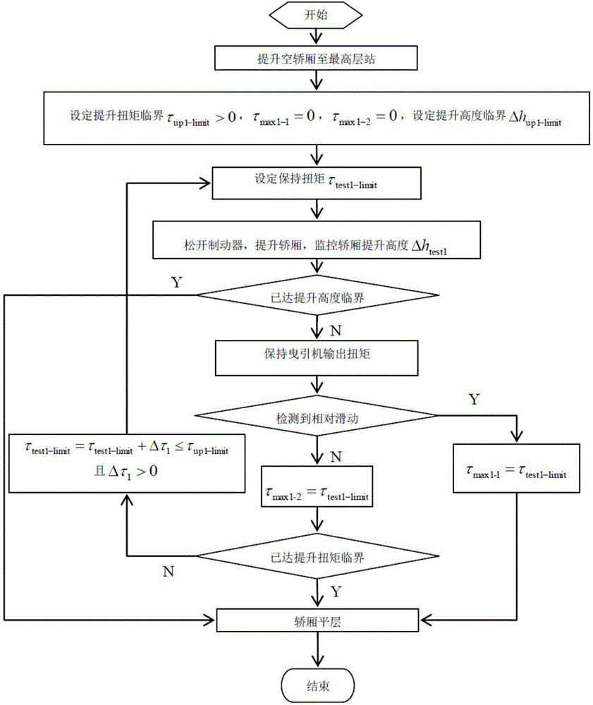
[0101] figure 1 is a schematic diagram of the detection method of the present embodiment, figure 2 is the flow chart of the steps of the present embodiment, image 3 is a schematic diagram of torque application in this embodiment. according to figure 1 , figure 2 , image 3 , the specific implementation process of this embodiment is:
[0102] 1. Lift the empty car 10 to the highest floor station;
[0103] 2. Define the upward direction of the traction sheave 40 to lift the car 10 as the positive direction of torque, let τ max1-1 represents the friction torque boundary 1, and τ max1-1 =0,τ max1-2 represents the friction torque boundary II, and τ max1-2 =0, and set the critical value of traction machine lifting torque Among them, T 1-1 is the internal tension of the traction rope on the car side when the elevator is at the highest floor with no load, f 1 In order to use the reference friction coefficient μ according to the groove shape 1 (0.1≤μ 1 ≤0.2) The calcu...
Embodiment 2
[0119] figure 1 is a schematic diagram of the detection method of the present embodiment, Figure 4 is the flow chart of the steps of the present embodiment, Figure 5 is a schematic diagram of torque application in this embodiment. according to figure 1 , Figure 4 , Figure 5 , the specific implementation process of this embodiment is:
[0120] 1. Lift the empty car 10 to the highest floor station;
[0121] 2. Define the upward direction of the traction sheave 40 to lift the car 10 as the positive direction of torque, let τ max2 represents the friction torque, and τ max2 =0, and set the critical value of traction machine lifting torque Among them, T 1-2 is the internal tension of the traction rope on the car side when the elevator is at the highest floor with no load, f 2 In order to use the reference friction coefficient μ according to the groove shape 2 (0.1≤μ 2 ≤0.2) The calculated equivalent friction coefficient, α is the wrap angle of the traction rope;
...
Embodiment 3
[0133] Figure 6 is a schematic diagram of the detection method of the present embodiment, Figure 7 is the flow chart of the steps of the present embodiment, Figure 8 is a schematic diagram of torque application in this embodiment. according to Figure 6 , Figure 7 , Figure 8 , the specific implementation process of this embodiment is:
[0134] 1. Lower the empty car 10 to the lowest landing;
[0135] 2. Define the upward direction of the traction sheave 40 to lift the car 10 as the positive direction of torque, let τ max3-1 represents the friction torque boundary 1, and τ max3-1 =0, let τ max3-2 represents the friction torque boundary II, and τ max3-2 =0, and set the critical value of traction machine lifting torque Among them, T 2-3 is the internal tension of the traction rope 50 on the counterweight side when the elevator is at the lowest floor with no load, f 3 In order to use the reference friction coefficient μ according to the groove shape 3 (0.1≤μ 3 ...
PUM
 Abstract
Description
Claims
Application Information
 - R&D
- Intellectual Property
- Life Sciences
- Materials
- Tech Scout
- Unparalleled Data Quality
- Higher Quality Content
- 60% Fewer Hallucinations
Browse by: Latest US Patents, China's latest patents, Technical Efficacy Thesaurus, Application Domain, Technology Topic, Popular Technical Reports.
© 2025 PatSnap. All rights reserved.Legal|Privacy policy|Modern Slavery Act Transparency Statement|Sitemap|About US| Contact US: help@patsnap.com


