Novel locomotive lifting beam

A technology for hoisting beams and locomotives, applied in the directions of load hoisting components, transportation and packaging, can solve the problems of large occupied space, poor passability, large volume, etc., and achieve the effects of stable structure, improved passability, and reduced welding requirements.

Inactive Publication Date: 2014-09-03
CRRC QISHUYAN CO LTD
View PDF10 Cites 2 Cited by
  • Summary
  • Abstract
  • Description
  • Claims
  • Application Information

AI Technical Summary

Problems solved by technology

[0003] In order to overcome the shortcomings of the existing locomotive lifting device, such as large volume, large space occupation, poor passability and easy collision, the present invention provides a new type of locomotive lifting beam

Method used


Image

  • Novel locomotive lifting beam
  • Novel locomotive lifting beam
  • Novel locomotive lifting beam

Examples


Embodiment Construction

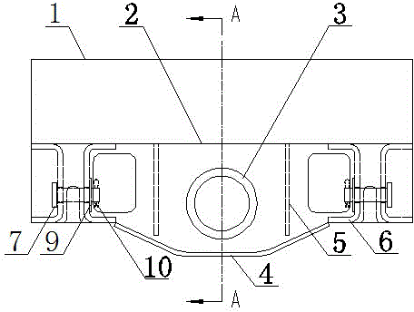
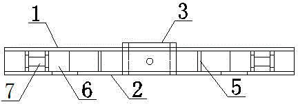
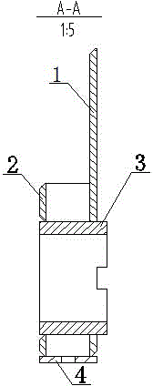
[0016] Such as figure 1 It is a structural schematic diagram of the present invention, figure 2 is a top view of the present invention, image 3 It is A-A sectional view of the present invention, Figure 4 It is a schematic diagram of the connection between the present invention and the bogie hanger, a new type of locomotive lifting beam, including an inner plate 1, an outer plate 2, a crane barrel 3, a bottom plate 4, a rib plate 5 and a lifting seat 6, and the two ends of the bottom plate 4 are respectively connected At the bottom of the inner panel 1 and the outer panel 2, the lifting seat 6 is sandwiched between the inner panel 1 and the outer panel 2 to form a frame structure. The lifting seat 6 is provided with a pin shaft 7, and a lifting rope is provided on the pin shaft 7. 8. The ribs 5 are vertically connected between the inner panel 1 and the outer panel 2 . The two ends of bearing pin 7 are respectively inserted in two adjacent lifting seats 6. A washer 9 and...


PUM


Abstract

The invention relates to the technical field of internal combustion engines, and particularly relates to a novel locomotive lifting beam. The novel locomotive lifting beam comprises an internal plate, an external plate, a crane cylinder, a base plate, rib plates and lifting seats, wherein two ends of the base plate are respectively connected to the bottom parts of the internal plate and the external plate; the lifting seats are clamped between the internal plate and the external plate so as to form a framework structure. The novel locomotive lifting beam is stable in structure, the structural rigidity is further enhanced by the rib plates, and an integrated lifting beam structure is formed, the intensity is improved, the welding requirement is lowered, and the lifting safety of a finished vehicle is guaranteed; moreover, the lifting seats are configured in the lifting beam, so that the problem of interference with a bogie during passing process in a curved mode is avoided, and the passing capacity is improved.

Description

technical field [0001] The invention relates to the technical field of diesel locomotives, in particular to a novel locomotive lifting beam. Background technique [0002] When the locomotive is being transported or in some special working conditions, it is necessary to lock the bogie and frame and lift the whole locomotive. The original locking lifting device is to respectively weld hangers on the lifting beam and bogie frame, and lock the bogie and vehicle frame with hoisting ropes. Considering strength and safety issues, the hanger must be large enough, and the welding requirements are high. For some locomotives with small margins, such a large-size hanger is likely to interfere with the bogie when passing a curve, which affects the passability. , and easily cause collisions. Contents of the invention [0003] In order to overcome the shortcomings of the existing locomotive lifting device, which are bulky, occupy a large space, have poor passability, and easily cause c...

Claims


Application Information

Patent Timeline
Patent Type & Authority Applications(China)
IPC IPC(8): B66C1/20
Inventor 周雄邢莹莹
Owner CRRC QISHUYAN CO LTD
Why Eureka
Try Eureka