Bearing block for speed reducer

A bearing seat and reducer technology, applied in the direction of mechanical equipment, transmission parts, belts/chains/gears, etc., can solve problems such as inability to achieve deceleration, failure to meet the normal operation of the reducer, shaft vibration, etc., to ensure stability Effect

Inactive Publication Date: 2014-09-03
陈焕祥
View PDF8 Cites 0 Cited by
  • Summary
  • Abstract
  • Description
  • Claims
  • Application Information

AI Technical Summary

Problems solved by technology

The existing installation bearing seat of the input shaft and output shaft of the reducer generally only includes the base and the extension part fixedly connected with the base. Since the bearing seat has no other mechanism for fixing the auxiliary shaft, most of the shafts often vibrate The phenomenon makes the gear installed on the shaft vibrate, which cannot meet the normal operation of the reducer and cannot achieve the purpose of its deceleration.

Method used


Image

  • Bearing block for speed reducer
  • Bearing block for speed reducer
  • Bearing block for speed reducer

Examples


Embodiment Construction

[0015] The present invention is described in further detail now in conjunction with accompanying drawing. These drawings are all simplified schematic diagrams, which only illustrate the basic structure of the present invention in a schematic manner, so they only show the configurations related to the present invention.

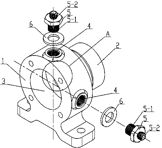
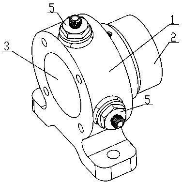
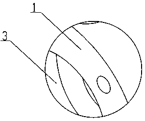
[0016] Such as figure 1 , figure 2 and image 3 The shown bearing housing for the reducer includes a base 1, on which a protruding part 2 is fixedly installed, and a bearing hole 3 is jointly opened on the base 1 and the protruding part 2, and on the upper end surface and the side surface of the base 1 Each threaded hole 4 is provided, and each threaded hole 4 is provided with a fastener 5 matching the threaded hole 4 .

[0017] The fastener 5 includes a fastening screw 5-1 connected to the threaded hole 4 and a threaded portion 5-2 disposed on the upper surface of the fastening screw 5-1 and integrally formed with the fastening screw 5-1. A washer 6 is a...


PUM


Abstract

The invention relates to the technical field of bearing blocks, in particular to a bearing block for a speed reducer. The bearing block comprises a base, an extending part is fixedly installed on the base, the base and the extending part are provided with bearing holes, and the upper end face and the side face of the base are provided with threaded holes which are provided with fasteners matched with the threaded holes. According to the bearing block for the speed reducer, the installation position of a shaft can be adjusted by adjusting the lengths of the parts, extending into the threaded holes, of the fasteners, and the operation stability of the shaft is guaranteed.

Description

technical field [0001] The invention relates to the technical field of bearing seats, in particular to a bearing seat for a reducer. Background technique [0002] The reducer is generally used for transmission equipment with low speed and high torque. The power of the electric motor, internal combustion engine or other high-speed operation is achieved by the gear with a small number of teeth on the input shaft of the reducer meshing with the large gear on the output shaft to achieve the purpose of deceleration. The ratio of the number of teeth is the transmission ratio. The existing installation bearing seat of the input shaft and output shaft of the reducer generally only includes the base and the extension part fixedly connected with the base. Since the bearing seat has no other mechanism for fixing the auxiliary shaft, most of the shafts often vibrate The phenomenon makes the gear installed on the shaft vibrate, which cannot meet the normal operation of the reducer, and...

Claims


Application Information

Patent Timeline
IPC IPC(8): F16H57/021
CPCF16H57/021
Inventor 陈焕祥
Owner 陈焕祥
Why Eureka
Try Eureka