Camera-inertial sensor calibration method based on partial sensor information

An inertial sensor and calibration method technology, applied in the field of camera-inertial sensor calibration in computer vision, can solve the problems of increasing system error, large yaw angle error, and inability to effectively reduce system cumulative error

Active Publication Date: 2017-03-01
PEKING UNIV SHENZHEN GRADUATE SCHOOL
View PDF3 Cites 2 Cited by
  • Summary
  • Abstract
  • Description
  • Claims
  • Application Information

AI Technical Summary

Problems solved by technology

At present, the low-cost and low-end inertial sensors on the market can output the roll angle (Roll angle) and the pitch angle (Pitch angle) of the three-axis direction angle with high accuracy, but the error of the output yaw angle (Yaw angle) relatively bigger
If the yaw angle information with large error output by the inertial sensor is directly used to assist the monocular vision SLAM system, not only cannot effectively reduce the cumulative error of the system, but will further increase the system error due to the introduction of a large yaw angle error

Method used


Image

  • Camera-inertial sensor calibration method based on partial sensor information
  • Camera-inertial sensor calibration method based on partial sensor information
  • Camera-inertial sensor calibration method based on partial sensor information

Examples


Embodiment Construction

[0053] The technical solutions in the embodiments of the present invention will be clearly and completely described below in conjunction with the accompanying drawings in the embodiments of the present invention. It should be understood that the described embodiments are only some of the embodiments of the present invention, not all of them. example. Based on the embodiments of the present invention, all other implementations obtained by those skilled in the art without creative efforts fall within the protection scope of the present invention.

[0054] 1. System functions:

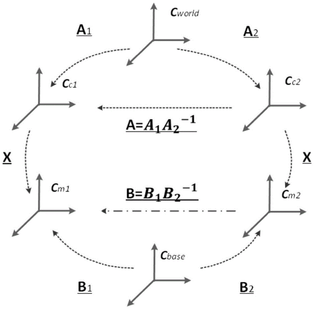
[0055] The traditional camera-inertial sensor calibration problem is theoretically reduced to solving a matrix equation:

[0056] R A R=RR B

[0057] This equation is called the calibration equation, as attached figure 1 shown. The camera and inertial sensor observe at two different poses, C C1 and C m1 are the coordinate system of the camera and the inertial sensor in the first pose state, C C2 ...


PUM


Abstract

The invention discloses a camera-inertial sensor calibration method based on partial sensor information. The method includes the steps that first, a calibration equation based on partial inertial sensor information is established, afterwards, the missing information of an inertial sensor is recovered first, then the relative coordinate transformation between a camera and the inertial sensor is solved, so that the calibration equation based on partial inertial sensor information is solved, and the calibration result is optimized. The camera-inertial sensor calibration problem is solved under the condition that the output information of the inertial sensor is incomplete, in the practical calibration environment, under the condition that observation errors exist, the final calibration result can be optimized through a designed optimization algorithm, and good calibration precision is achieved.

Description

technical field [0001] The invention belongs to the field of camera-inertial sensor calibration in computer vision, is applied in simultaneous localization and mapping (SLAM) technology, and specifically relates to a camera and an inertial sensor under the condition that the output information of the inertial sensor is incomplete The calibration method of coordinate system transformation between. Background technique [0002] Synchronous positioning and map creation refers to the fact that a mobile object perceives the environment through its own sensors without knowing its own position, creates a map consistent with the environment in an unknown environment, and simultaneously determines its position and posture in the map . In recent years, with the further development of technologies such as computer vision, synchronous positioning and map creation technology based on monocular vision has gradually become a research hotspot. Considering the shortcomings of a single perc...

Claims


Application Information

Patent Timeline
Patent Type & Authority Patents(China)
IPC IPC(8): G06T7/70G06T7/80
Inventor 刘宏周玉龙张国栋
Owner PEKING UNIV SHENZHEN GRADUATE SCHOOL
Why Eureka
Try Eureka