
Motion conversion experiment device in thermodynamic system

A technology of motion conversion and experimental equipment, applied in teaching models, educational tools, instruments, etc., can solve the problems that the reversible process of Brownian motion is stagnant, and the assumption of orderly motion of microscopic particles has not been verified and affirmed.

Inactive Publication Date: 2014-09-03
李纪军
View PDF0 Cites 2 Cited by
  • Summary
  • Abstract
  • Description
  • Claims
  • Application Information

AI Technical Summary

Problems solved by technology

It is this conclusion that makes the preconceived thinking about Maxwell's demon related to "energy must be consumed to obtain information", thus making the research on the reversible process of Brownian motion meaningless and stagnant
[0005] Therefore, due to various reasons, the previous assumptions about the movement of microscopic particles from disorder to order have not been verified and affirmed in the end.

Method used


Image

  • Motion conversion experiment device in thermodynamic system
  • Motion conversion experiment device in thermodynamic system
  • Motion conversion experiment device in thermodynamic system

Examples


Embodiment 1

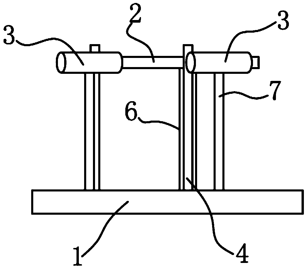
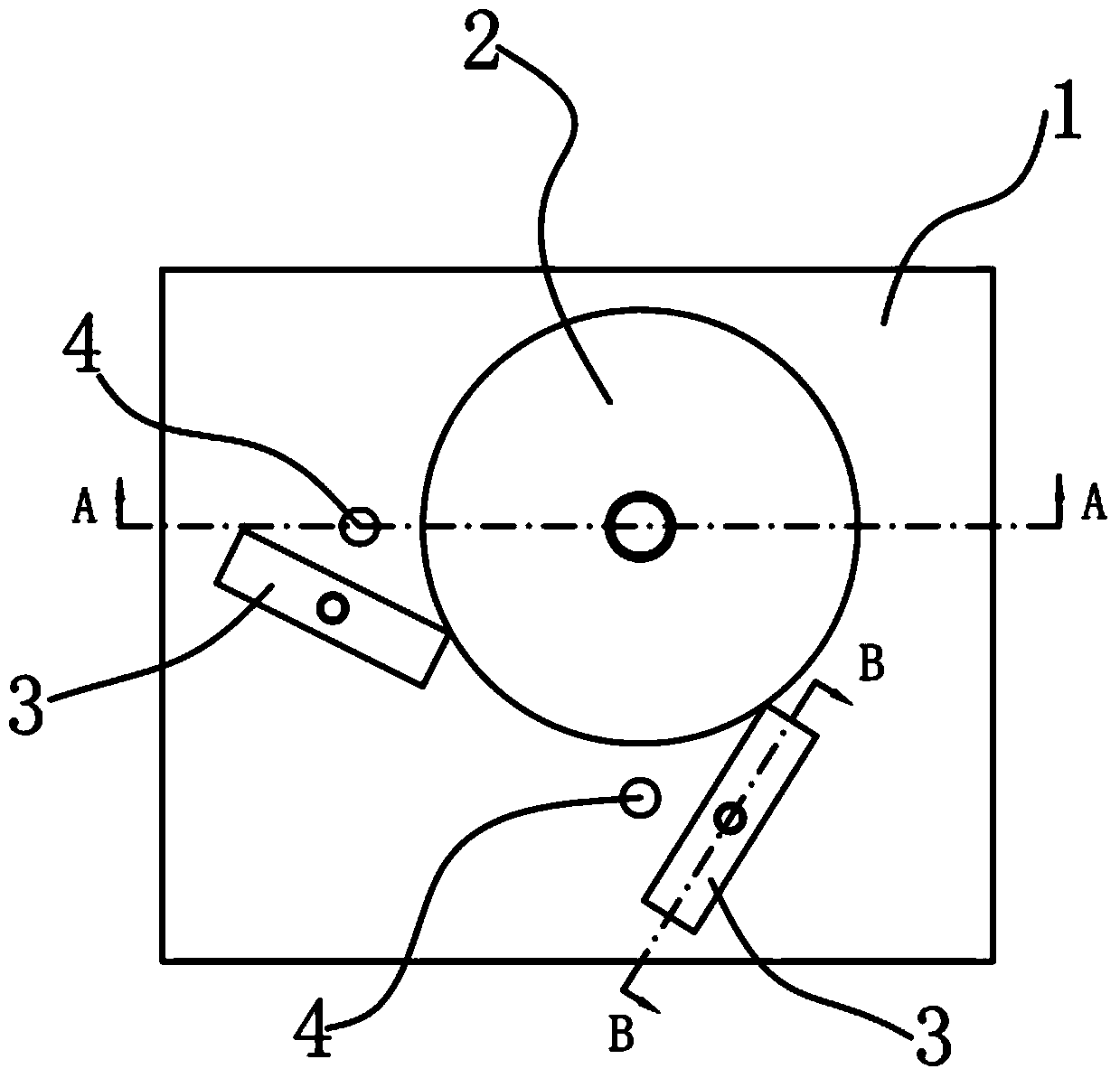
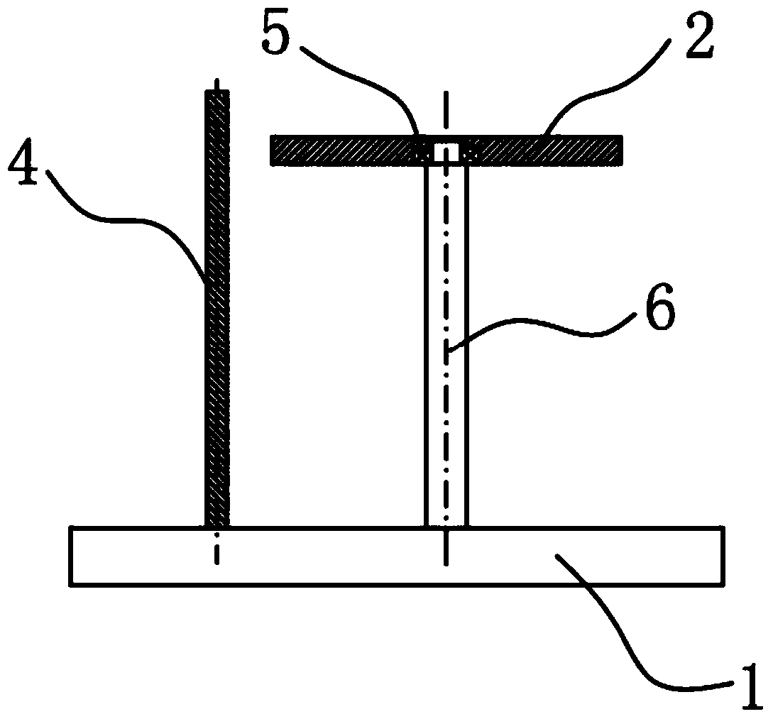
[0031] Such as Figure 1-4 As shown, the experimental device for motion conversion in a thermodynamic system according to the embodiment of the present invention mainly includes a base 1, a cyclic motion device, a plurality of elastic cylinders 3 distributed around the cyclic motion device, and corresponding to the elastic cylinder 3 Obstacle body 4, circulation device and elastic column body 3 are all flexibly connected with base 1, and obstacle body 4 is all arranged on the same side of elastic column body 3, and when elastic column body 3 rotates under the effect of external force (Brownian motion), the obstacle body 4 is used to restrict the elastic cylinder 3, so that the elastic cylinder 3 hits the cyclic movement device in one direction.

[0032] A preferred embodiment, the circular motion device is a disc 2, the disc 2 is movably connected with the base 1 through the main shaft 6, the elastic cylinder 3 is movably connected with the base 1 through the corresponding sid...

Embodiment 2

[0071] Such as Figure 11 As shown, the embodiment of this embodiment is basically the same as that of Embodiment 1, the difference is that the cyclic motion device is a belt transmission mechanism, which mainly includes a conveyor belt 8 and a pulley 9, and the pulley 9 moves with the base 1 through the corresponding main shaft 6 Connection, the two ends of the conveyor belt 8 are installed on the pulley 9, the elastic cylinder 3 is movably connected with the base 1 through the corresponding side shaft 7, the elastic cylinder 3 hits the conveyor belt 8 in one direction, and the pulley 9 and the elastic cylinder 3 pass through the rolling bearing It is connected with the corresponding main shaft 6 and the side shaft 7 .

[0072] Continuously move the elastic cylinder 3 by hand, the elastic cylinder 3 cannot collide with the conveyor belt 8 due to the obstruction of the obstacle 4 when it rotates counterclockwise, and when it rotates clockwise, the elastic cylinder 3 continuous...


PUM


Abstract

The invention discloses a motion conversion experiment device in a thermodynamic system, which mainly comprises a base, a circulation motion device, a plurality of elastic column bodies distributed around the circulation motion device and barriers corresponding to the elastic column bodies, wherein the circulation motion device and the elastic column bodies are all movably connected with the base; the barriers are arranged at the same sides of the elastic column bodies; when the elastic column bodies rotates under the effect of external force, the barriers are used for limiting the elastic column bodies to enable the elastic column bodies to impact the circulation motion device in single direction. An ideal machine is amplified to manufacture a simulation device normally observed by the naked eye, the elastic column bodies rotating around fixed axes impact the circulation motion device in single direction, continuous single-direction rotation can be realized, an amplification model manufactured by converting fluctuation in an air system into directionally-rotating mechanical energy in the way is realized, the process is successfully simulated, and accuracy of microscopic particles from disordered motion to ordered motion.

Description

technical field [0001] The invention belongs to the field of physical experiment devices, in particular to a motion conversion experiment device in a thermodynamic system. Background technique [0002] As early as 1901, Perrin, who confirmed the existence of atoms with Brownian motion experiments, pointed out that Brownian motion is a reversible process, so it will lead to short-term or local entropy reduction, which undoubtedly strongly questions the second law of thermodynamics. But as we all know, the research on this (entropy reduction caused by fluctuations) has disappeared. Because it is generally believed that the second law of thermodynamics is a statistical law that only applies to a large range of situations. Since it is a "statistical law, applicable to a wide range of situations", why not further study the microscopic process? What led to the termination of this process was the appearance and influence of the "Maxiwell Demon". In 1867, Maxwell mentioned in a l...

Claims


Application Information

Patent Timeline
IPC IPC(8): G09B23/16
Inventor 李纪军
Owner 李纪军
Learn More