Microwave four-frequency power divider

A power divider and microwave technology, applied in waveguide devices, electrical components, connecting devices, etc., can solve the problems of difficult bandwidth adjustment and complex structure, and achieve the effects of easy planarization, good matching, and simple circuit structure

Inactive Publication Date: 2014-09-03
NANJING UNIV OF AERONAUTICS & ASTRONAUTICS
View PDF7 Cites 4 Cited by
  • Summary
  • Abstract
  • Description
  • Claims
  • Application Information

AI Technical Summary

Problems solved by technology

[0006] The invention provides a microwave four-frequency power divider to solve the multi-frequency work of the power divider, realize the problems of complex structure, difficult bandwidth adjustment, etc., which can be realized by using PCB technology, and only need less debugging

Method used


Image

  • Microwave four-frequency power divider
  • Microwave four-frequency power divider
  • Microwave four-frequency power divider

Examples


Embodiment Construction

[0020] The technical solution of the present invention will be further described in detail below in conjunction with the accompanying drawings.

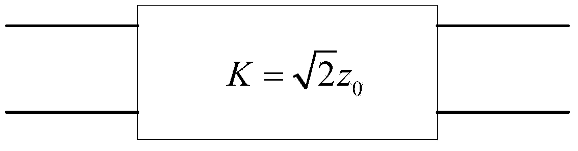
[0021] figure 1 A K-converter structure diagram of a Wilkinson power divider is given. The impedance transformation function of the K converter enables the input impedance at the input port and the input transmission line to achieve impedance matching, thereby reducing power reflection loss.

[0022] Its ABCD matrix is:

[0023] A = 0 ± jK ± 1 jK 0

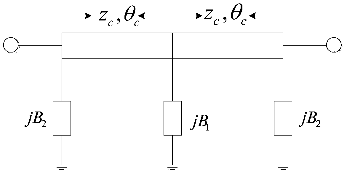
[0024] figure 2 Is the structure diagram of the four-frequency K-converter. The four-frequency impedance converter is composed of two identical transmission lines and three pairs of...


PUM


Abstract

The invention discloses a microwave four-frequency-band power divider and belongs to the field of multi-frequency power dividers. The four-frequency power divider comprises an isolation resistor and two four-frequency impedance transformers of the same structure. Each four-frequency impedance transformer is formed by two sections of identical transmission lines and three pairs of combined stub lines. Each combined stub line is formed by two open-circuit stub lines which can be in parallel connection or two short-circuit stub lines which can be in parallel connection or an open-circuit stub line and a short-circuit stub line which can be in parallel connection. The two four-frequency impedance transformers of the same structure are in parallel connection, the isolation resistor is uploaded, and accordingly the four-frequency power divider is achieved. The two pairs of combined stub lines are respectively arranged on the two sides of the two sections of the transmission lines, and the other pair of the combined stub lines is arranged in the middle of the two sections of transmission lines. The four-frequency power divider is simple in circuit design, planar in distribution, low in cost and less in debugging. Furthermore, the four-frequency power divider can be achieved through PCB process in a microstrip circuit mode.

Description

Technical field: [0001] The invention relates to a microwave four-frequency power divider, which belongs to the field of multi-frequency power dividers. Background technique: [0002] The implementation schemes of the existing multi-frequency power divider generally have the following types: [0003] 1) Expand the transmission line of the output port of the power divider. By selecting the appropriate characteristic impedance, electrical length and isolation resistance to achieve dual-frequency operation, the structure is simple, but it is not suitable for the design of high-order multi-frequency power dividers. [0004] 2) A three-frequency power divider is realized by using a T-shaped open-circuit branch line or a short-circuit branch line instead of a quarter-wavelength transmission line. The T-shaped stub line is not only complex in structure, but it is difficult to extract structural parameters so that it has an impedance transformation characteristic similar to that o...

Claims


Application Information

Patent Timeline
Patent Type & Authority Applications(China)
IPC IPC(8): H01P5/16
Inventor 缪细洋刘云
Owner NANJING UNIV OF AERONAUTICS & ASTRONAUTICS
Why Eureka
Try Eureka