
Frequency-adjustable array type piezoelectric cantilever beam energy harvester and frequency-adjustable array type piezoelectric cantilever beam energy harvesting method

A cantilever beam, array technology, applied in piezoelectric effect/electrostrictive or magnetostrictive motors, generators/motors, electrical components, etc., can solve the problems of large size of the drive device and high energy consumption in the frequency modulation link. , to achieve the effect of compact structure and improved energy capture efficiency

Inactive Publication Date: 2014-09-03
XIAMEN UNIV
View PDF3 Cites 13 Cited by
  • Summary
  • Abstract
  • Description
  • Claims
  • Application Information

AI Technical Summary

Problems solved by technology

At present, the self-frequency regulation energy harvesting technology is not yet mature, and there are major problems such as the large size of the drive device and the excessive energy consumption of the frequency regulation link.

Method used


Image

  • Frequency-adjustable array type piezoelectric cantilever beam energy harvester and frequency-adjustable array type piezoelectric cantilever beam energy harvesting method
  • Frequency-adjustable array type piezoelectric cantilever beam energy harvester and frequency-adjustable array type piezoelectric cantilever beam energy harvesting method
  • Frequency-adjustable array type piezoelectric cantilever beam energy harvester and frequency-adjustable array type piezoelectric cantilever beam energy harvesting method

Examples


Embodiment Construction

[0026] The present invention will be further described in conjunction with the accompanying drawings and specific embodiments.

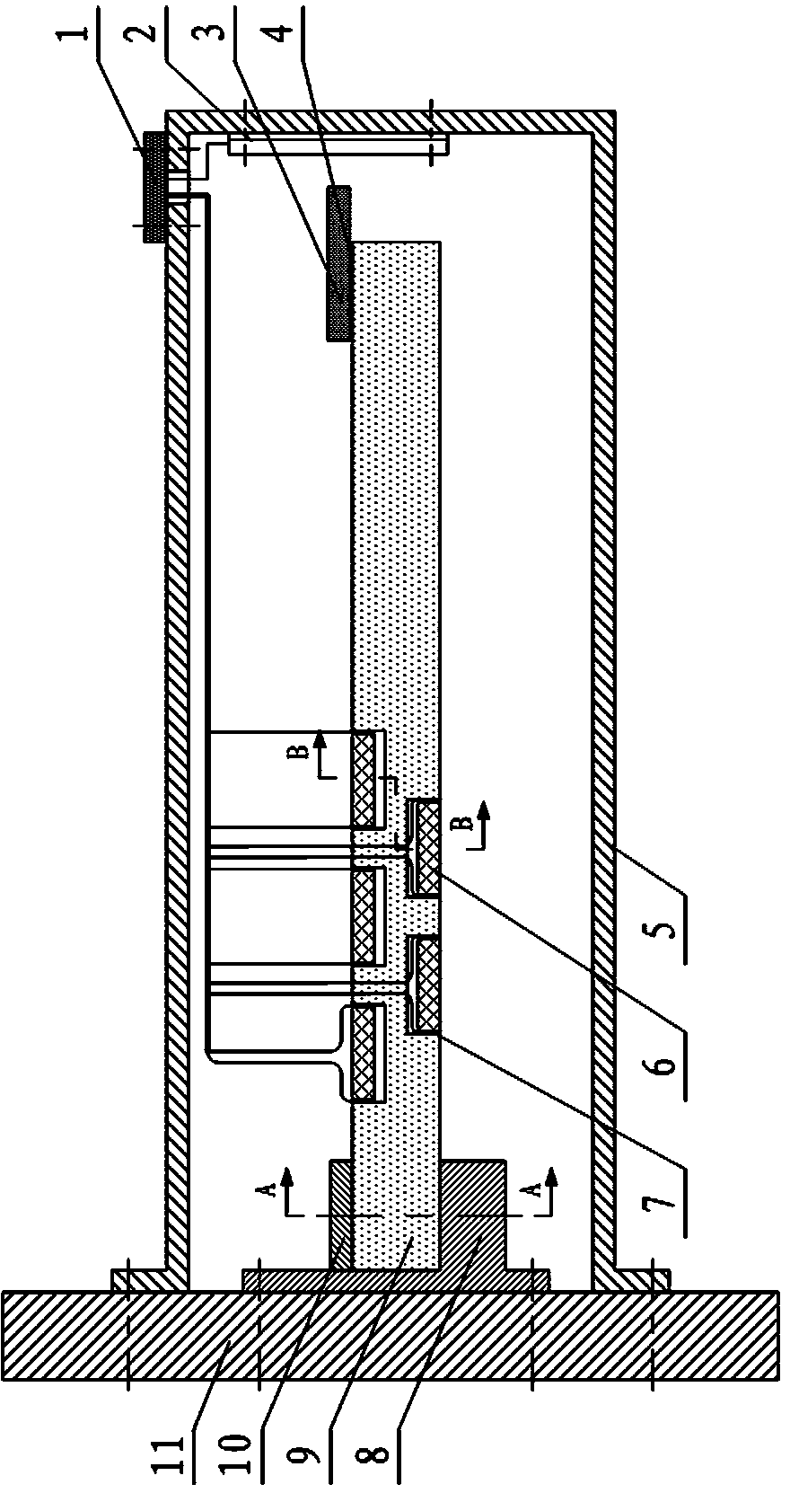
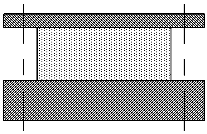
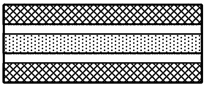
[0027] As a specific example, such as figure 1 As shown, a frequency-adjustable array piezoelectric cantilever beam energy harvester of the present invention includes a base 11, a fixed base 8, a cover plate 10, a housing and a cantilever beam, and the housing is a cover-shaped housing. The housing is fixedly connected to the base. Specifically, the housing 5 is mounted on the base 11 by screws, and an accommodation cavity is formed between the housing and the base. The fixed base 8 is arranged in the accommodation cavity and is connected to the base. Fixed connection, specifically, the fixed base 8 is installed on the base 11 by screws, the fixed base 8 is an L-shaped base 8, the cover plate is fixed on the opposite side of the L-shaped base, the cantilever One end of the beam is sandwiched between the L-shaped base and the cover plate, and the bas...


PUM


Abstract

The invention provides a frequency-adjustable array type piezoelectric cantilever beam energy harvester with a compact structure and high energy efficiency. Through separately arranging a plurality of piezoelectric stacks on two opposite side surfaces of an aluminum alloy substrate in an array manner, frequency adjustment is realized through different frequency adjusting capabilities of the piezoelectric stacks. Furthermore resonant frequency of the energy harvester can be efficiently adjusted automatically according to the vibrating frequency of surrounding environment automatically. Simultaneously, the invention further provides a frequency-adjustable array type piezoelectric cantilever beam energy harvesting method for the piezoelectric energy harvester. Position information of the free end of the piezoelectric cantilever beam is detected through combination of a magnet and a Hall sensor, and is input to a control circuit. The control circuit calculates according to the position information for obtaining latest electric field boundary condition values of a plurality of piezoelectric stack arrays. Furthermore a control signal is transmitted to the plurality of piezoelectric stack arrays for updating the latest electric field boundary condition values.

Description

technical field [0001] The invention relates to the technical field of new energy and power generation technology, in particular to a frequency-adjustable array piezoelectric cantilever energy harvester and a frequency-adjustable array piezoelectric cantilever energy harvesting method, which are used for low-frequency and environmental vibration frequencies within a certain range Vibrational energy harvesting for changes. Background technique [0002] In recent years, with the development of low-energy portable electronic devices and self-powered sensors or sensor networks, powering these low-energy electronic systems has become a topic of much interest. In order to overcome the problems of low battery life and troublesome replacement caused by battery power supply, the energy harvesting technology that utilizes the energy of the surrounding environment has received a lot of attention and development. In the field of vibration energy harvesting, piezoelectric energy harvest...

Claims


Application Information

Patent Timeline
Patent Type & Authority Applications(China)
IPC IPC(8): H02N2/18
Inventor 关明杰赵扬李营泰
Owner XIAMEN UNIV
Learn More