Eureka AIR delivers breakthrough ideas for toughest innovation challenges, trusted by R&D personnel around the world.

Curved tube for endoscope

A technology for bending tubes and endoscopes, applied to the field of bending tubes for endoscopes, can solve the problems of difficulty in obtaining a bending shape, changes in bending characteristics of the bending tubes, etc.

Active Publication Date: 2014-09-03
OLYMPUS CORP
View PDF8 Cites 25 Cited by
  • Summary
  • Abstract
  • Description
  • Claims
  • Application Information

AI Technical Summary

Problems solved by technology

[0005] However, in the case where the wire guide is integrally formed with the bending tube body as in the technique disclosed in Patent Document 1, the bending characteristics of the bending tube may locally change at places such as the front and rear of the wire guide.
Therefore, if the bending characteristics change locally in this way, it may be difficult to obtain a desired curved shape such as bending the curved tube into a uniform arc shape.

Method used


Image

  • Curved tube for endoscope
  • Curved tube for endoscope
  • Curved tube for endoscope

Examples


Embodiment Construction

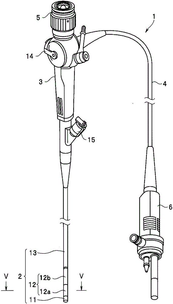
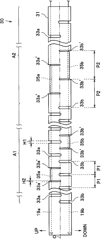
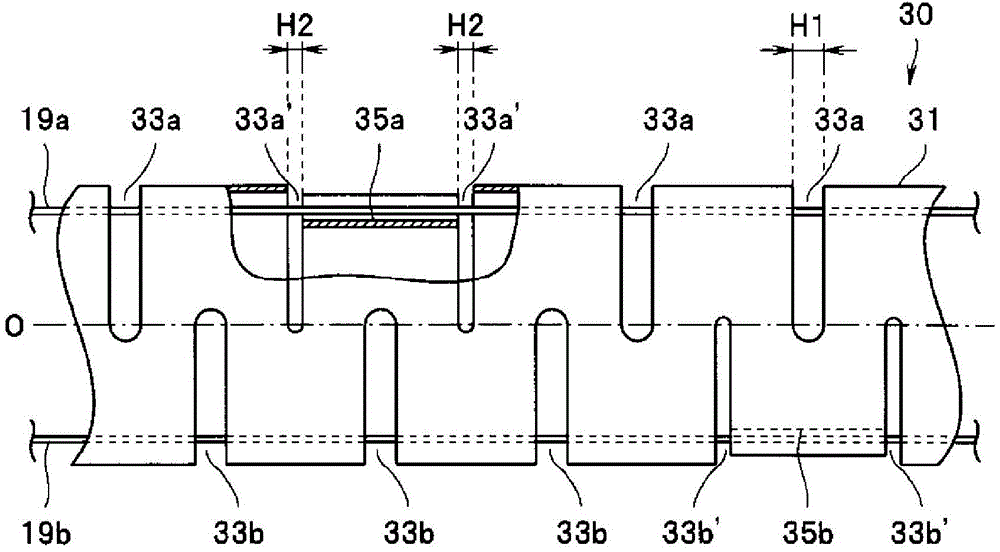
[0033] Hereinafter, embodiments of the present invention will be described with reference to the drawings. The drawings relate to the first embodiment of the present invention, figure 1 is a stereogram of an endoscope, figure 2 is the side view of the curved tube, image 3 It is a side view showing the main part of the curved pipe partially cut away, Figure 4 is a perspective view showing the main part of the curved pipe, Figure 5 is along figure 1 The sectional view of the main part of the V-V line, Figure 6 is an explanatory diagram showing the minimum radius of curvature of a curved pipe, Figure 7 It is an explanatory diagram showing the minimum radius of curvature of the curved tube when the slit width is not adjusted as a comparative example.

[0034] Such as figure 1 As shown, the endoscope 1 is, for example, a so-called fiberscope that mainly includes a long insertion portion 2, an operation portion 3, a universal cable 4, an eyepiece portion 5, and a connec...


PUM


Abstract

A curved tube (30) is equipped with the following: a plurality of first curving slots (33a) that are provided at set intervals along a longitudinal axis (O) direction of a cylindrical curved tube body (31) and that extend in the circumferential direction of the curved tube body (31); wire guide-forming slots (first curving slots (33a')) provided forming a pair with respect to the arrangement of the plurality of first curving slots (33a) and extending in the peripheral direction of the curved tube body (31); and a wire guide (35a) formed by deforming an outer peripheral part of the curved tube body (31) in the inner radial direction between the wire guide forming-slots forming a pair. The curved tube (30) wherein the width (H2) of the curving slots (33a') adjacent to the wire guide (35a) is set to be relatively narrower than the width (H1) of the other curving slots (33a).

Description

technical field [0001] The present invention relates to a bending tube for an endoscope that bends in response to an operation of an operation unit. Background technique [0002] Conventionally, an endoscope that displays an image of a subject in a body cavity on a screen of a display device by inserting an elongated insertion portion into the body cavity has been widely used. Among such endoscopes, for example, in a flexible endoscope having a flexible insertion portion, the insertion portion is configured by sequentially connecting a distal hard portion, a bending portion, and a flexible tube portion from the distal end side. [0003] The bending portion is configured to be able to bend freely in two directions up and down, in two directions left and right, or in four directions up, down, left and right, for example, corresponding to the subject image displayed on the display device. In order to enable such a bending operation, generally, the bending portion is configured...

Claims


Application Information

Patent Timeline
Patent Type & Authority Applications(China)
IPC IPC(8): A61B1/00
CPCA61M25/0138F16L11/00A61B1/0057A61B1/0055
Inventor 佐藤荣二郎格雷戈里·空斯托罗姆
Owner OLYMPUS CORP
Why Eureka
Eureka Blog
Learn More