Automatic loading and unloading device

An automatic loading and unloading and feeding technology, which is applied in metal processing and other directions, can solve problems such as industrial accidents and fatigue, and achieve the effects of fast feeding, compact structure and reasonable design

Active Publication Date: 2014-09-10
江苏瑞普机床有限公司
View PDF4 Cites 2 Cited by
  • Summary
  • Abstract
  • Description
  • Claims
  • Application Information

AI Technical Summary

Problems solved by technology

[0003] In the past, the processing of such parts was still manually loaded and unloaded, and employees worked mechanically, which was prone to fatigue and lead to work-related accidents; "If a worker wants to do a good job, he must first sharpen his tools

Method used


Image

  • Automatic loading and unloading device
  • Automatic loading and unloading device
  • Automatic loading and unloading device

Examples


Embodiment Construction

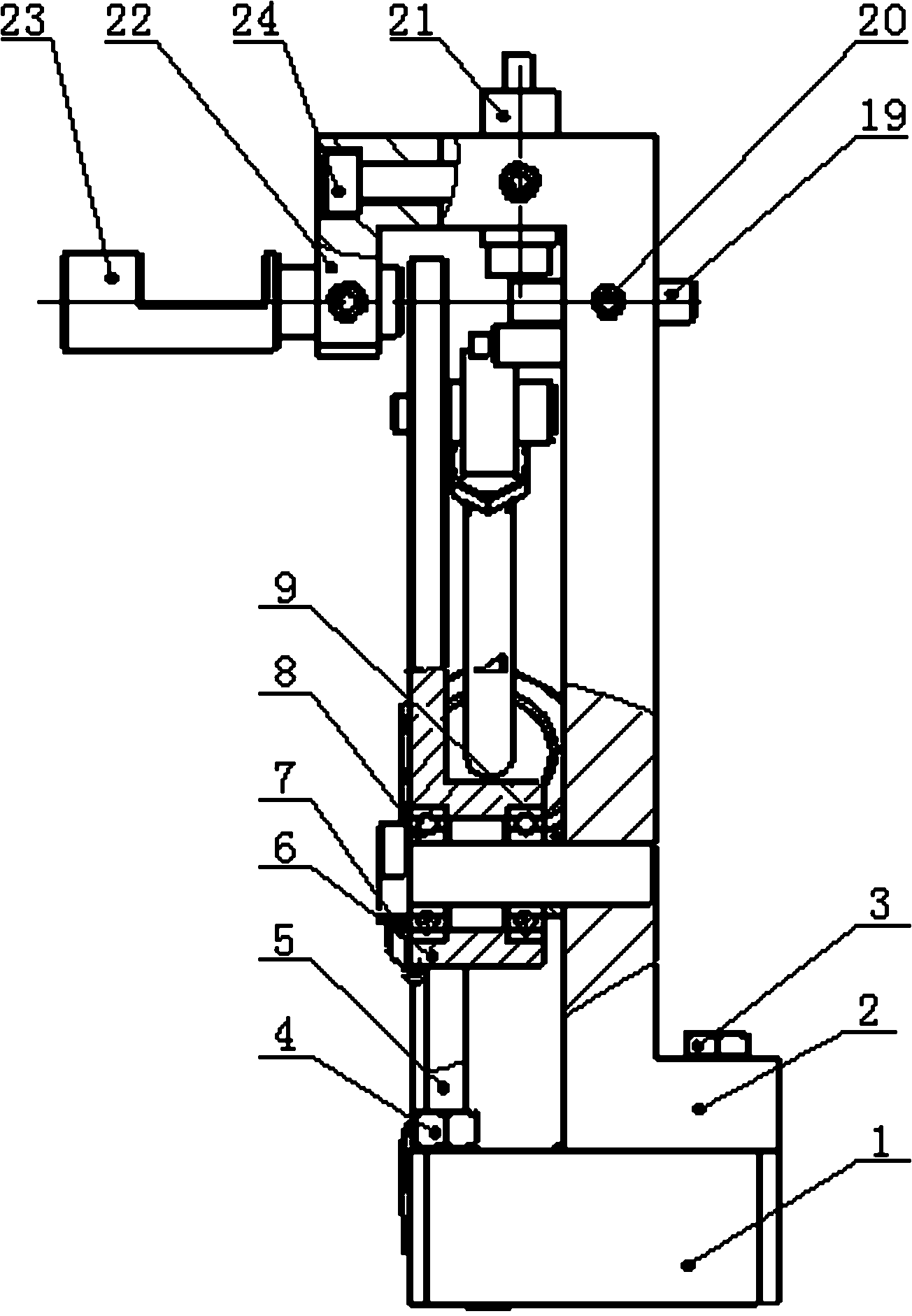
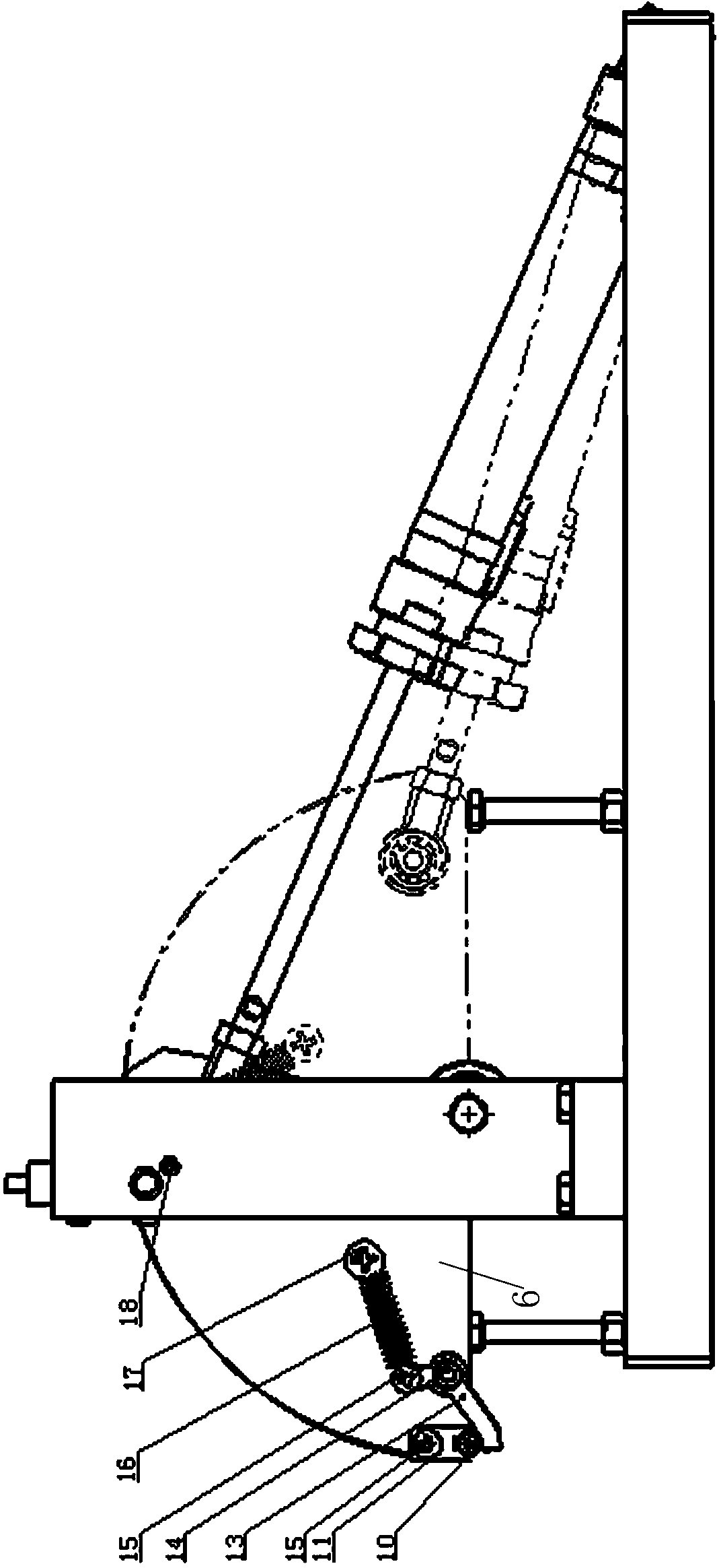
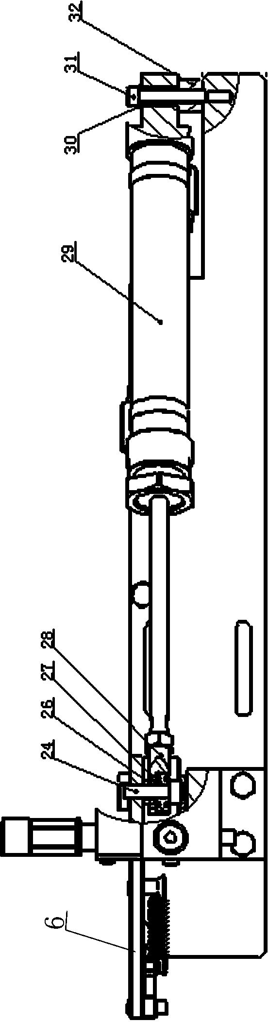
[0014] Refer to attached figure 1 , 2 , 3. An automatic loading and unloading device includes a bottom plate 1, a bracket 2, a feeding tray 6, a small shaft 7, two deep groove ball bearings 8, a large spacer 9, a "V"-shaped positioning block 11, a movable pressing block 13, Extension spring 16, back plate 19, induction switch 21, feeding support 22, feeding guide sleeve 23, small spacer ring 26, union 28, cylinder 29, rotating shaft 32 and flat gasket 31.

[0015] The bracket 2 is fixed on the bottom plate 1 by two hexagonal bolts 3; the two hexagonal socket head screws 5 are fixed on the bottom plate 1, which are used to adjust the feeding and returning position of the feeding tray 6, and are tightened with two hexagonal nuts 4 to prevent loosening; Two deep groove ball bearings 8 are installed in the disc 6, the small shaft 7 passes through its inner hole and the large spacer 9, and the feeding disc 6 is fixed on the side of the bracket 2; the front end of the feeding disc ...


PUM


Abstract

The invention relates to an automatic loading and unloading device, in particular to an automatic loading and unloading device used on a precision machining tool in a matched manner. The automatic loading and unloading device comprises a bottom plate, a bracket, a feed plate, a small shaft, two deep groove ball bearings, a large space ring, a V-shaped locating block, a movable pressing block, a tension spring, a back plate, an inductive switch, a feed bracket, a feed guide sleeve, a small space ring, a loose joint, a cylinder, a rotating shaft and a flat gasket, wherein the bracket is fixed on the bottom plate through two hexagon bolts; the two deep groove ball bearings are mounted in the feed plate, the small shaft penetrates through an inner hole of the feed plate and the large space ring to fix the feed plate on the side surface of the bracket; the V-shaped locating block is fixed at the front end of the feed plate through one cross recessed screw; the movable press block is fixed on the feed plate by an inner hexagon screw, the rear end of the movable press block is connected with one end of the tension spring through one cross recessed screw, and the other end of the tension spring is fixed on the feed plate through one cross recessed screw; the back plate is fixed on the bracket through inner hexagon flat-end set screws II; and the inductive switch is fixed at the upper part of the bracket.

Description

technical field [0001] The invention relates to an automatic loading and unloading device, specifically an automatic loading and unloading device matched with a precision machining machine tool. Background technique [0002] The spool part of the oil delivery valve is an internal combustion engine product part, GCr15 material, material hardness 179-207HB, and 4 grooves are processed in equal parts on the outer circle after the product is clamped. [0003] In the past, the processing of such parts was still manually loaded and unloaded, and employees were mechanically labored, which was prone to fatigue and lead to work-related accidents; At the same time, the machine tool must be used in conjunction with reasonable fixtures to effectively ensure the processing quality of the workpiece, improve labor productivity, expand the scope of use of the machine tool and reduce labor intensity. Contents of the invention [0004] The purpose of the present invention is to provide an ...

Claims


Application Information

Patent Timeline
Patent Type & Authority Applications(China)
IPC IPC(8): B23Q7/00
CPCB23Q7/00
Inventor 金伟伍永刚陈福来
Owner 江苏瑞普机床有限公司
Why Eureka
Try Eureka