

Attachment Structure Of Weight Sensor For Seat Occupant Detection
A technology of weight sensor and attachment structure, which is applied in the direction of vehicle seat, pedestrian/occupant safety layout, application, etc. It can solve the problems of too long signal line, increased sensor cost, and difficult sensor attachment work, etc., and achieve cost reduction Effect
- Summary
- Abstract
- Description
- Claims
- Application Information
AI Technical Summary
Problems solved by technology
Method used
Image

Examples
no. 1 approach )
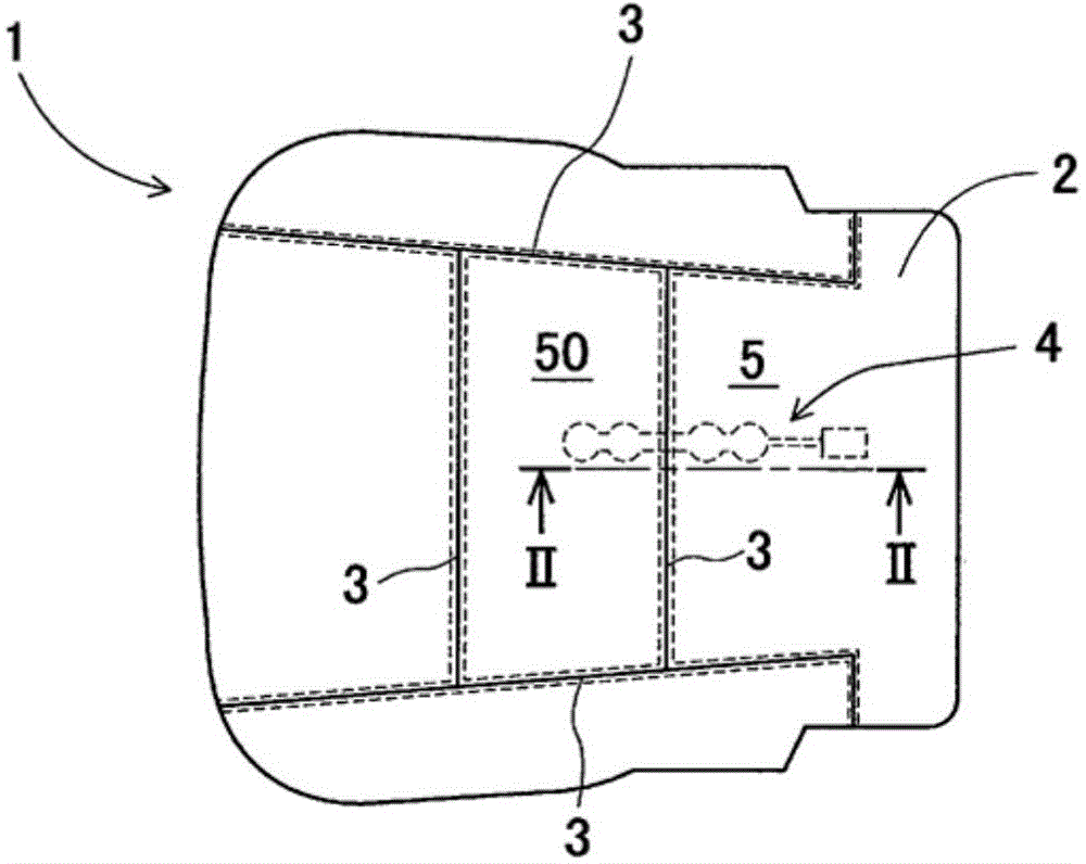
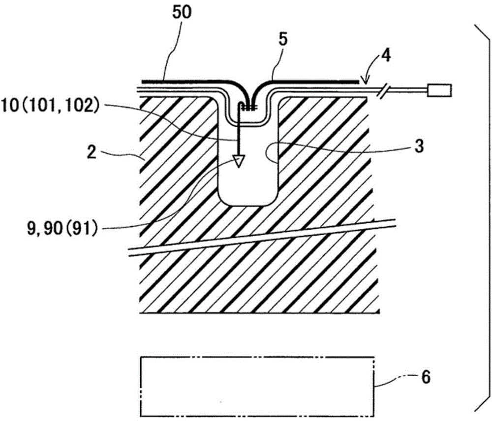
[0020] Such as figure 1 and 2 As shown in , a seat portion 1 of a vehicle includes a seat cushion member 2 , skin members 5 and 50 , and a weight sensor 4 . The seat cushion member 2 is made of, for example, urethane, and has cushioning properties to be used as a base of the seat. The skin members 5 and 50 are made of fabric, artificial leather or leather and surround the upper and side surfaces of the seat cushion member 2 . The weight sensor 4 is interposed between the cushion member 2 and the skin member 5 .
[0021] The upper surface of the cushion member 2 has a plurality of grooves 3 and the skin members 5 and 50 are drawn into the grooves 3 to match the geometry of the surface of the cushion member 2 . The skin members 5 and 50 are pulled by using the insertion member 10 , the connection members 9 and 90 , and an unillustrated fixing tool for the connection members 9 and 90 . A method of pulling the skin members 5 and 50 into the groove 3 will be described below. A...
no. 2 approach )
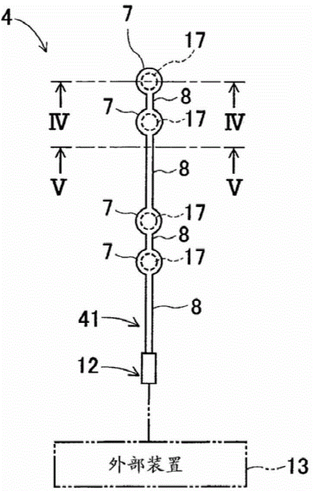
[0042] Such as figure 2 and 7 As shown in , the end portion of the skin member 5 and the end portion of the skin member 50 are coupled together with the end portion of the insertion member 101 in the central portion of the opening of the groove 3, so that the skin members 5, 50 and the insertion A connecting line 241 is created between the components 101 . More specifically, the sides of the end portions of the skin members 5 and 50 are aligned with the sides of the end portion of the insertion member 101 in the same line, ie, in the joining line 241 . The insertion member 101 is made of fabric, for example, and may be in the shape of a bag.
[0043] The insertion member 101 has an opening portion 111 on the opposite side of the insertion member 101 with respect to the coupling line 241 . The opening portion 111 has a rectangular opening that opens on both sides of the insertion member 101 and communicates with the external space on the opposite side of the insertion membe...
no. 3 approach )
[0046] Such as figure 2 and 8 As shown in , the end portion of the skin member 5 and the end portion of the skin member 50 are coupled together with the end portion of the insertion member 102 in the central portion of the opening of the groove 3, so that the skin members 5, 50 and the insertion A joining line 242 is created between the components 102 . More specifically, the sides of the end portions of the skin members 5 and 50 and the sides of the end portion of the insertion member 102 are aligned in the same line, ie, the joining line 242 . The insertion member 102 is made of fabric, for example, and may be in the shape of a bag.
[0047] The opposite side of the insertion member 102 with respect to the coupling line 242 is connected to the connection member 91 . The connection member 91 may be, for example, a resin rod or a metal wire. The connection member 91 is inserted into the insertion member 102 when the insertion member 102 has a bag shape. The insertion mem...
PUM
 Abstract
Description
Claims
Application Information