
Linear compressor and oil lubricating method thereof

A linear compressor and oil supply technology, which is applied in mechanical equipment, machines/engines, liquid displacement machines, etc., can solve the problems of easy clogging of micropores, increase of production cost, difficulty in ensuring reliability, etc., and prevent wear and tear , the effect of improving performance

Active Publication Date: 2014-09-10
QINGDAO HAIER SMART TECH R & D CO LTD
View PDF5 Cites 13 Cited by
  • Summary
  • Abstract
  • Description
  • Claims
  • Application Information

AI Technical Summary

Problems solved by technology

This kind of gas bearing can ensure the lubrication effect between the piston and the cylinder during high-frequency movement. However, the gas bearing has a strong dependence on the machining accuracy of the cylinder and piston, and the micropores are easy to be blocked, and its long-term operation reliability Difficult to guarantee
In addition, due to the low viscosity of the gas, in order to ensure the sealing effect of the compression chamber, the specified gap between the cylinder and the piston is often required to be small, resulting in high processing accuracy and easy to increase the production cost
[0009] It can be seen that the above two bearings of the existing linear compressor still have defects in improving the performance of the linear compressor and ensuring the reliability

Method used


Image

  • Linear compressor and oil lubricating method thereof
  • Linear compressor and oil lubricating method thereof

Examples


Embodiment Construction

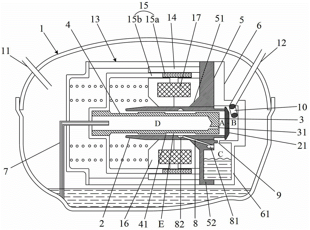
[0036] Refer below figure 2 Shown is a detailed description of the specific implementation of the linear compressor of the present invention.

[0037] Such as figure 2 As shown, both the flange 5 and the cylinder head 6 are in the shape of an asymmetric disk. The flange 5 has a flange side wall 52 located below the exhaust chamber B, and the cylinder head 6 has a flange located under the exhaust chamber B. The lower cylinder head side wall 61 is oppositely arranged with a certain distance between them, and the edge of the flange side wall 52 and the edge of the cylinder head side wall 61 are bent toward each other and butted against each other, thereby , the side wall 52 of the flange and the side wall 61 of the cylinder head jointly form a cavity, which is the oil storage cavity C. A narrow opening 9 is provided between the exhaust chamber B and the oil storage chamber C, and the two are communicated through the narrow opening 9 . Through the narrow opening 9, the circul...


PUM


Abstract

The invention provides a linear compressor and an oil lubricating method thereof. The linear compressor comprises an outer casing which accommodates refrigerating mediums and lubricating oil; an air cylinder, a piston and a piston shaft are arranged inside the outer casing; a gap is formed between the air cylinder and the piston shaft; a flange plate is configured on the outer peripheral surface of the air cylinder; an air cylinder cover is fixed on the flange plate; an exhaust valve is arranged on the internal side of the air cylinder cover on the end portion of the air cylinder; space which is defined by the piston, the air cylinder and the air cylinder cover is separated into a compression chamber and an exhaust chamber which are communicated through the exhaust valve; the linear compressor is provided with an oil storage air chamber which is communicated with the exhaust chamber and the gap; the lubricating oil is connected with the compression chamber through an oil suction pipe; the lubricating oil enters into the compression chamber through the oil suction pipe due to relative movement between the piston and the air cylinder; the lubricating oil and the refrigerating mediums are mixed inside the compression chamber to form into high pressure gas-oil mixture; the high pressure gas-oil mixture is discharged into the exhaust chamber; partial high pressure gas-oil mixture enters into the oil storage chamber and the gap is full of the partial high pressure gas-oil.

Description

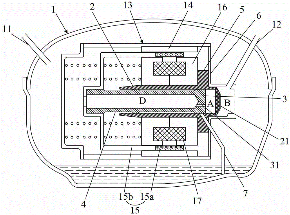
technical field [0001] The invention relates to a linear compressor and an oil supply lubrication method thereof. Background technique [0002] Such as figure 1 As shown, the conventional linear compressor has a casing 1, and a recess is formed at the bottom of the casing 1, and lubricating oil is stored in the recess. The shell 1 is also provided with an air intake pipe 11 for leading the refrigerant medium into the shell 1 and an exhaust pipe 12 for leading the refrigerant medium out. A cylindrical housing 13 is accommodated in the housing 1, and a cylindrical outer stator 14, a mover 15, an inner stator 16, and a motor placed in the inner stator 16 are accommodated in the housing 13. Coil 17, cylinder 2 and other components, wherein the cylinder 2 is centrally arranged in the housing 13 along its axial direction, and the piston 3 and the piston shaft 4 integrally formed with it are placed in the cylinder 2 . An inner stator 16 is sleeved on the outer peripheral surface...

Claims


Application Information

Patent Timeline
IPC IPC(8): F04B35/04F04B39/02F04B39/12F04B39/00
Inventor 闫赛娜李衡国宋斌赵志强许升李标
Owner QINGDAO HAIER SMART TECH R & D CO LTD
Learn More