Compressor pump body structure and compressor

A technology for compressors and pumps, applied in machines/engines, components of pumping devices for elastic fluids, rotary piston/oscillating piston pump components, etc., can solve the problems of contact, increased power consumption, roller and flange gap reduction, etc., to achieve the effect of increasing basic strength, reducing power consumption, and reducing deformation

Active Publication Date: 2017-03-15
ZHUHAI LANDA COMPRESSOR +1
View PDF9 Cites 0 Cited by
  • Summary
  • Abstract
  • Description
  • Claims
  • Application Information

AI Technical Summary

Problems solved by technology

When the compressor is running, such as Figure 5 As shown, the flange bears the overturning moment. Since the thickness of the valve seat area is smaller than that of other areas, when the eccentric part of the crankshaft rotates to this area, under the action of the overturning moment, the working surface of the valve seat area will have a larger convex deformation than other areas, changing The shape can cause the gap between the roller and the flange to decrease, or even cause the two to come into contact, thereby increasing the power consumption

Method used


Image

  • Compressor pump body structure and compressor
  • Compressor pump body structure and compressor
  • Compressor pump body structure and compressor

Examples


Embodiment 1

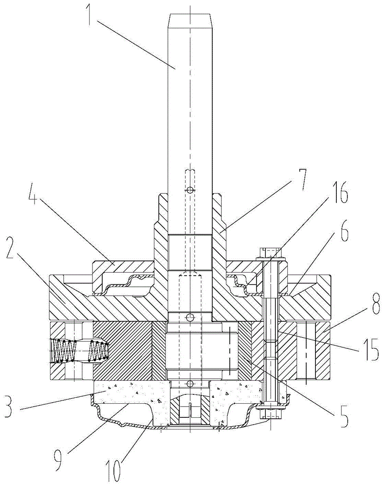
[0030] Such as figure 1 , 2 As shown, a pump body structure of a compressor includes: crankshaft 1, upper flange 2, lower flange 3, roller 5, cylinder 8 and support 4; upper flange 2 and lower flange 3 are set on On the crankshaft 1, the upper flange 2 and the lower flange 3 are fixedly connected with the cylinder 8, and the roller 5 is arranged between the upper flange 2 and the lower flange 3; the upper flange 2 includes the non-working surface 6 of the upper flange, The lower flange 3 includes the non-working surface 9 of the lower flange; the non-working surface 6 of the upper flange is the surface of the upper flange 2 facing away from the roller 5, and the non-working surface 9 of the lower flange is the surface of the upper flange 3 facing away from the roller 5 The support member 4 abuts on the non-working surface 6 of the upper flange and / or the non-working surface 9 of the lower flange, and is fixedly connected with the upper flange 2 and / or the lower flange 3 .

...

Embodiment 2

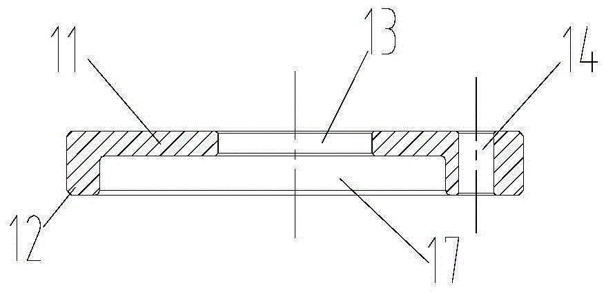
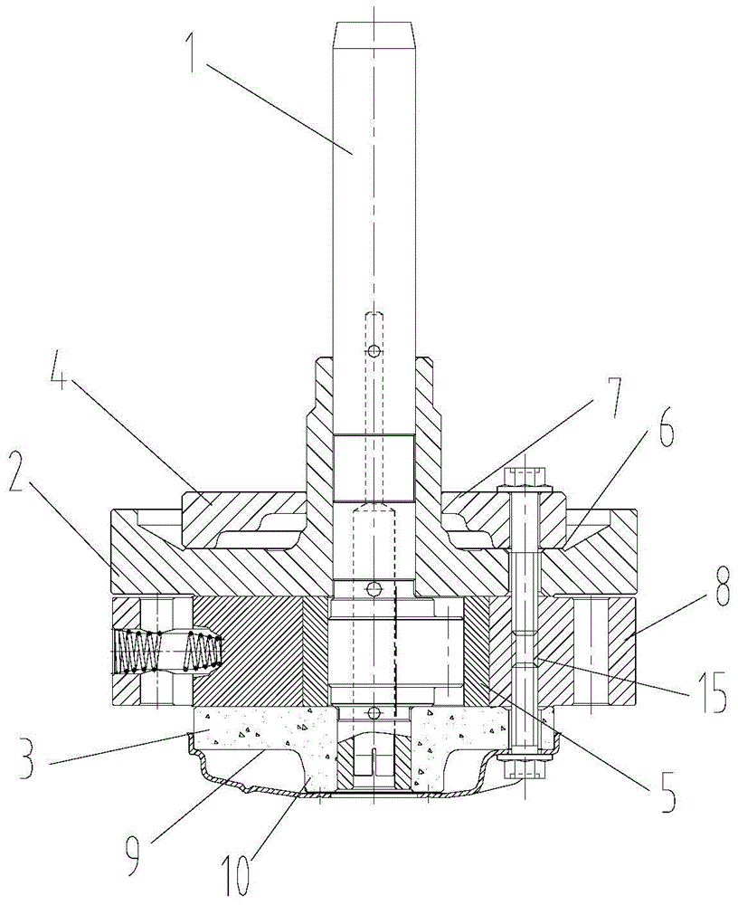
[0037] Such as image 3 , 4 As shown, this embodiment has the same structural features as the first embodiment, and the difference from the first embodiment is that the muffler 16 is omitted, and the inner wall of the accommodating space 17 is a step formed by a smooth curved surface. The inner wall of the accommodating space 17 is a step formed by a smooth curved surface. The design of the step formed by this smooth curved surface is the same shape as that of the inner wall of the muffler 16 in the embodiment, so that the passing air flow can be guided to achieve Noise reduction effect. In this way, the supporting member 4 can not only support the upper flange 2 and / or the lower flange 3, but also can silence the compressor, which saves the cost.

[0038] The present invention also provides a compressor, including the pump body structure of the compressor described in any of the above embodiments.

[0039] The invention has the advantages of reasonable design, simple struc...


PUM


Abstract

The invention provides a pump body structure of a compressor and the compressor. The pump body structure of the compressor comprises a crankshaft, an upper flange, a lower flange, a roller, a cylinder and a support piece, wherein the upper flange and the lower flange are both coated on the crankshaft, and are both fixedly connected with the cylinder; the roller is arranged between the upper flange and the lower flange; the upper flange comprises an upper flange non-working surface; the lower flange comprises a lower flange non-working surface; the support piece is butted to the upper flange non-working surface, and is fixedly connected with the upper flange; and / or, the support piece is butted to the lower flange non-working surface, and is fixedly connected with the lower flange. The pump body structure of the compressor has the advantages of reasonable design, simple structure and convenience for operation and installation, can enhance the basic intensity of the upper flange and / or the lower flange, and decreases the deformation of the upper flange and / or the lower flange so as to reduce the power consumption.

Description

technical field [0001] The invention relates to the technical field of home appliances, in particular to a pump body structure of a compressor and the compressor. Background technique [0002] With the development of science and technology, compressors are more and more widely used in household appliances. [0003] At present, the pump body of the existing rotary compressor is composed of a crankshaft, an upper flange and a lower flange sleeved on the crankshaft, a cylinder, a roller, a sliding vane and other components, such as Image 6 As shown, its exhaust port 19 is arranged on the flange (the single exhaust structure is generally on the upper flange, and the double exhaust structure and the double cylinder structure are then on the upper flange and the lower flange). In order to reduce the clearance volume, the mounting seat of the fixed exhaust valve (ie, the valve seat 18) is generally lower than the non-working surface of the flange, that is, the thickness of the val...

Claims


Application Information

Patent Timeline
Patent Type & Authority Patents(China)
IPC IPC(8): F04C29/00F04C29/06
Inventor 杨志强
Owner ZHUHAI LANDA COMPRESSOR
Why Eureka
Try Eureka