
Induced draught fan and boost fan combined control method for large thermal generator set

A technology for thermal power generating units and booster fans, applied in pump control, machines/engines, mechanical equipment, etc., can solve the problems of high booster fan power, low FGD inlet pressure, large safety margin, etc., and achieve responsive working conditions Effects of changing, stabilizing and optimizing operation

Inactive Publication Date: 2014-09-10
STATE GRID CORP OF CHINA +1
View PDF4 Cites 24 Cited by
  • Summary
  • Abstract
  • Description
  • Claims
  • Application Information

AI Technical Summary

Problems solved by technology

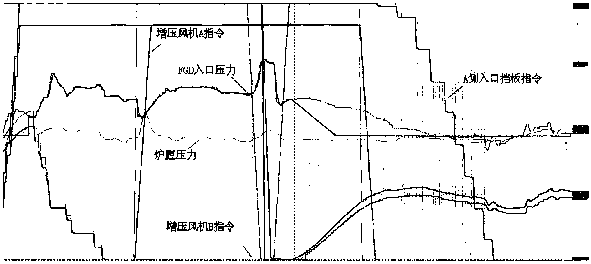
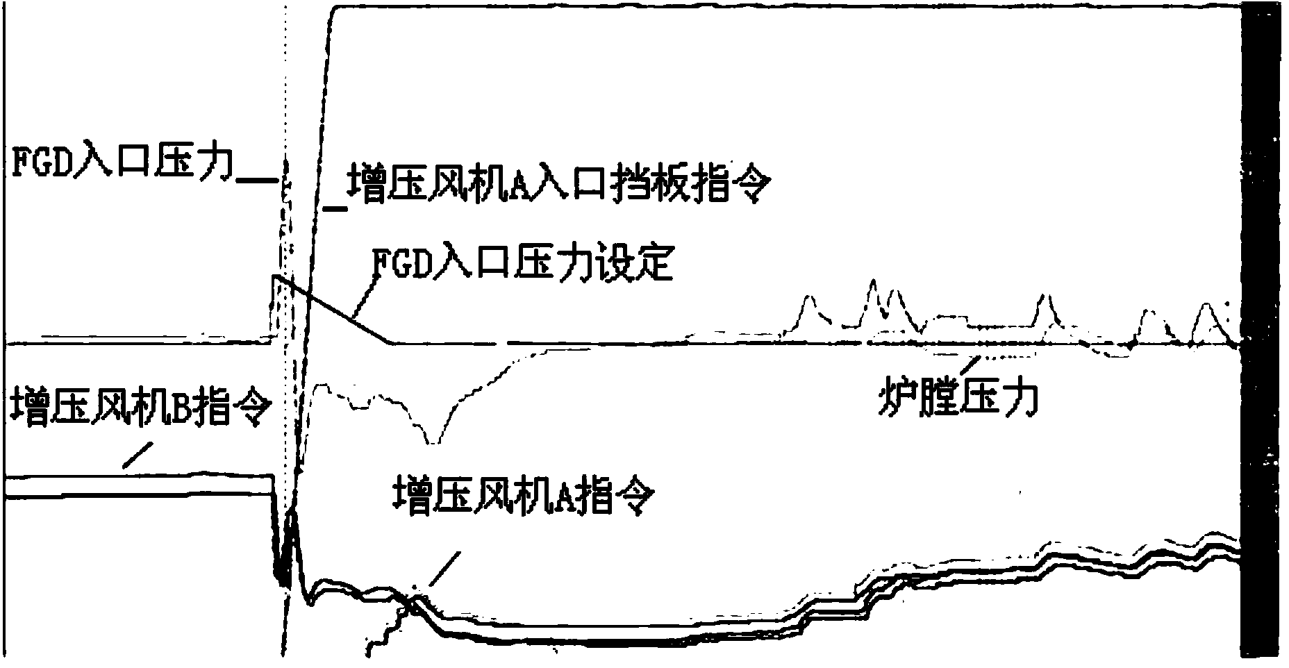
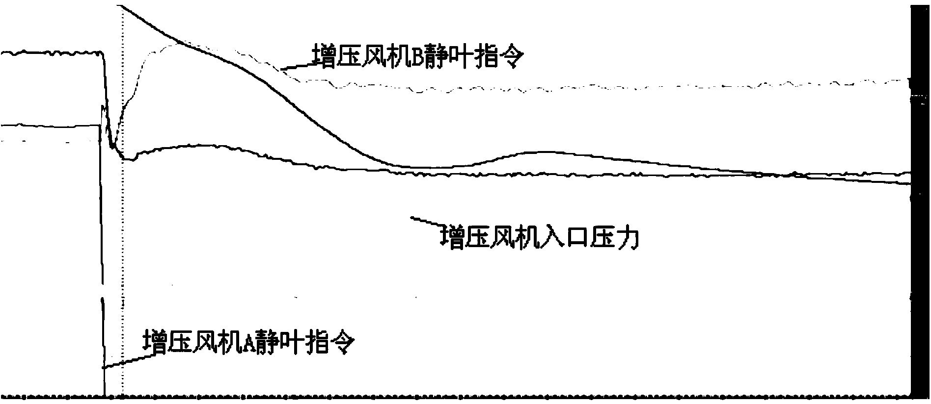
[0005] The power of the booster fan is large, and it is easy to cause the FGD inlet pressure to be too low when it is started, and even the bypass is opened quickly. After the bypass baffle is canceled, the control strategy needs to be improved. For the cooperation of the fan, especially when the second one is started, it is necessary to adjust the setting value of the booster fan and the control command synchronously, so that the FGD inlet pressure is controlled within 1000Pa, leaving a large safety margin for the equipment safety of the unit. quantity

Method used


Image

  • Induced draught fan and boost fan combined control method for large thermal generator set
  • Induced draught fan and boost fan combined control method for large thermal generator set
  • Induced draught fan and boost fan combined control method for large thermal generator set

Examples


Embodiment Construction

[0029] In order to illustrate the present invention more clearly, the present invention will be further described below in conjunction with preferred embodiments and accompanying drawings. Similar parts in the figures are denoted by the same reference numerals. Those skilled in the art should understand that the content specifically described below is illustrative rather than restrictive, and should not limit the protection scope of the present invention.

[0030] For clarity, the descriptions, abbreviations or abbreviations of the technical terms used in the following are summarized as follows:

[0031] Furnace Negative Pressure: The furnace negative pressure is a parameter reflecting the pressure in the furnace. There are two ways to express pressure: one is called absolute pressure (also known as real pressure), which is the pressure value obtained from absolute vacuum as the starting point of measurement. The other is called relative pressure, which is the pressure value...


PUM


Abstract

The invention discloses an induced draught fan and boost fan combined control method for a large thermal generator set. The thermal generator set comprises at least two induced draught fans and at least two boost fans. The control method includes the following portions, namely, stripping protection logic optimization of the induced draught fans and the boost fans, sequential control start step sequence optimization of the induced draught fans and the boost fans, the steps of the induced draught fan and boost fan combined control method in the normal running process, and the steps of the induced draught fan and boost fan combined control method under the abnormal working condition. By means of the method, the influences on pressure at the inlet of the FGD can be reduced when the boost fans are started; working condition changes can be responded to in time in the running process of the set; running of the set can be ensured by conducting adjustment in time through the RB method and other methods under the accident working condition; when device safety is influenced, interlocked stripping of the induced draught fans and the boost fans can be achieved, and the method has great significance in safe, stable and optimized running of the set.

Description

technical field [0001] The invention relates to a thermal power generating set, in particular to a combined control method for a large thermal generating set induced draft fan and a booster fan. Background technique [0002] According to the regulations of the country to dismantle the flue gas desulfurization bypass baffle door of thermal power units during the "Twelfth Five-Year Plan" period, all thermal power units need to block the bypass baffle door of the desulfurization flue gas system. After the desulfurization bypass baffle is blocked, the system must be fully adjusted to maintain the safe and stable operation of the unit in case of equipment abnormality, which has higher requirements for logical configuration and operation mode. If the booster fan and the induced draft fan are combined, the related control system is reduced. After the transformation, the flue gas goes directly from the outlet of the dust collector to the absorption tower through the induced draft fa...

Claims


Application Information

Patent Timeline
Patent Type & Authority Applications(China)
IPC IPC(8): F04D27/00
Inventor 尹峰戴航丹吴永存罗志浩金冯梁张永军陈波舒畅赵琦
Owner STATE GRID CORP OF CHINA
Learn More