LED (light emitting diode) illuminating lamp

A technology of LED lighting and LED light source, which is applied in the direction of lighting devices, lighting and heating equipment, lighting device components, etc., can solve the problems of high cost, unsightly, complex structure of LED lights, etc., and achieve low production cost and low structure. simple effect

Inactive Publication Date: 2014-09-10
LEEDARSON IOT TECH INC
View PDF5 Cites 8 Cited by
  • Summary
  • Abstract
  • Description
  • Claims
  • Application Information

AI Technical Summary

Problems solved by technology

[0004] However, this method of disposing heat sinks on the lamp cap of the LED lamp makes the current LED lamp complex in structure, high in cost and unattractive.

Method used


Image

  • LED (light emitting diode) illuminating lamp
  • LED (light emitting diode) illuminating lamp

Examples


Embodiment Construction

[0014] The present invention will be further described in detail below in conjunction with the accompanying drawings and specific embodiments.

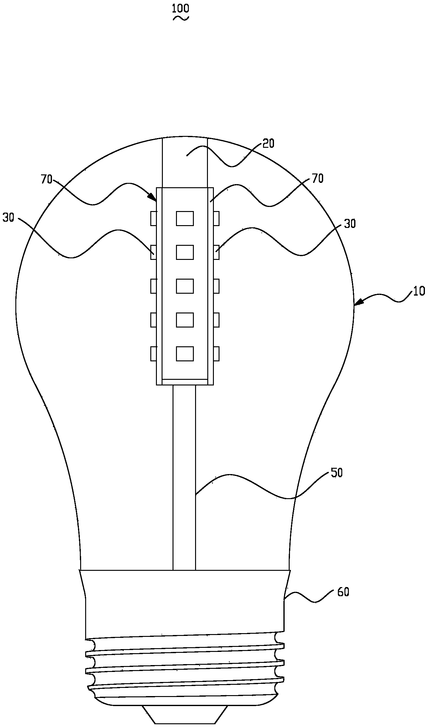
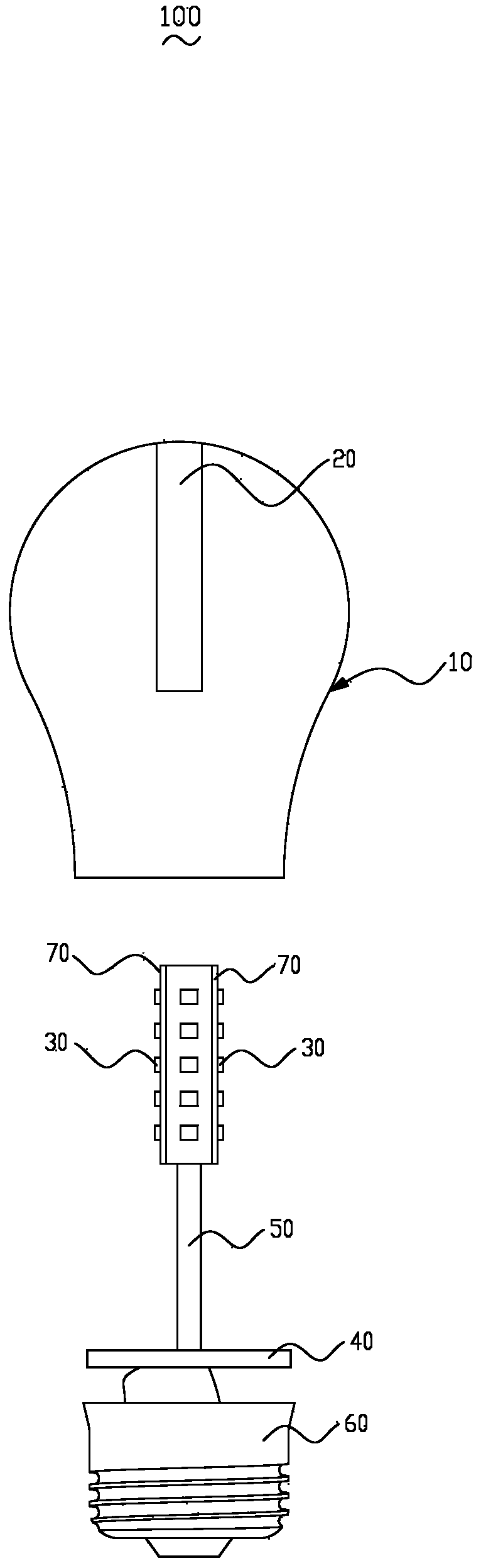
[0015] Please refer to figure 1 and figure 2 , the LED lighting lamp 100 includes a bulb shell 10 , an LED light source 30 , a heat conduction column 20 , a lamp head body 60 and a driving board 40 . The bottom of the bulb 10 is covered on the top of the lamp body 60 . One end of the heat conducting column 20 is thermally connected to the top of the bulb shell 10 . These LED light sources 30 are arranged on the heat conduction column 20 , and these LED light sources 30 are thermally connected with the heat conduction column 20 . The driving board 40 is arranged in the lamp head body 60 , and the LED light sources 30 are electrically connected with the driving board 40 through wires 50 .

[0016] Please refer to figure 2 , the bulb shell 10 is a hemispherical bulb shell structure, and the light bulb shell 10 is provided with a l...


PUM


Abstract

An LED (light emitting diode) illuminating lamp comprises a bulb shell, an LED light source and a lamp holder. The bottom of the bulb shell covers the top of the lamp holder. The LED illuminating lamp is characterized by also comprising a heat conduction column; one end of the heat conduction column is in thermal connection with the top of the bulb shell; the LED light source is arranged on the heat conduction column; and the LED light source is in thermal connection with the heat conduction column. Compared with the prior art, the LED illuminating lamp is provided with the heat conduction column, one end of the heat conduction column is in thermal connection with the top of the bulb shell, and heat generated by the LED light source is conducted to the bulb shell via the heat conduction column, and is dissipated outwards through the bulb shell. Because a heat sink which is connected with the lamp holder is not required, the LED illuminating lamp has the advantages of simple structure and low production cost.

Description

technical field [0001] The invention relates to an LED illuminating device, in particular to an LED illuminating lamp. Background technique [0002] Due to the advantages of energy saving and environmental protection, LED lights are becoming more and more popular, and have the advantages of high luminous efficiency, power saving and long life. When the LED light source emits light, its own temperature will gradually rise. During continuous operation, if the heat generated by the LED light source cannot be dissipated in time, the light source component will be damaged and the service life of the lighting device will be affected. [0003] The current technology is to arrange a heat sink on the lamp cap. For example: a Chinese invention patent with a publication date of July 27, 2012 and a patent number of 201210265420.3 discloses an LED bulb lamp. The LED bulb lamp includes a base plate, a heat sink and a bulb housing, the base plate is arranged on the top of the heat sink, ...

Claims


Application Information

Patent Timeline
Patent Type & Authority Applications(China)
IPC IPC(8): F21S2/00F21V29/00F21V3/00F21V19/00F21V23/00F21Y101/02F21K9/232F21Y107/00F21Y115/10
Inventor 郭伟杰孔凡聪李江淮
Owner LEEDARSON IOT TECH INC
Why Eureka
Try Eureka