Light guide column and lamps

A technology of light guide columns and lamps, which is applied in the direction of optics, light guides, light sources, etc., can solve the problems of small irradiation space, small light angle, and difficult injection molding, so as to ensure external aesthetics, improve distribution angle, and simple injection molding Effect

Active Publication Date: 2017-11-28
LEEDARSON IOT TECH INC
View PDF6 Cites 0 Cited by
  • Summary
  • Abstract
  • Description
  • Claims
  • Application Information

AI Technical Summary

Problems solved by technology

However, the light emitting angle of the current LED light source is relatively small, generally within 120 degrees. Therefore, compared with traditional incandescent lamps and halogen lamps, the light of LED lamps is more concentrated in the front, and the lateral illumination is uneven and the irradiation space is smaller.
[0003] In order to overcome the above-mentioned defects, in the related art, a light guide column is provided in the LED lamp, but the generally used light guide column is solid, and the designed LED lamp is limited by the inner light guide column, and the appearance is not beautiful enough; in addition , the existing light guide column, injection molding is relatively difficult, it is difficult to improve production efficiency, and the optical efficiency is not high, and the beam angle is difficult to enlarge

Method used


Image

  • Light guide column and lamps
  • Light guide column and lamps
  • Light guide column and lamps

Examples


Embodiment Construction

[0025] In order to have a clearer understanding of the technical features, purposes and effects of the present invention, the specific implementation manners of the present invention will now be described in detail with reference to the accompanying drawings.

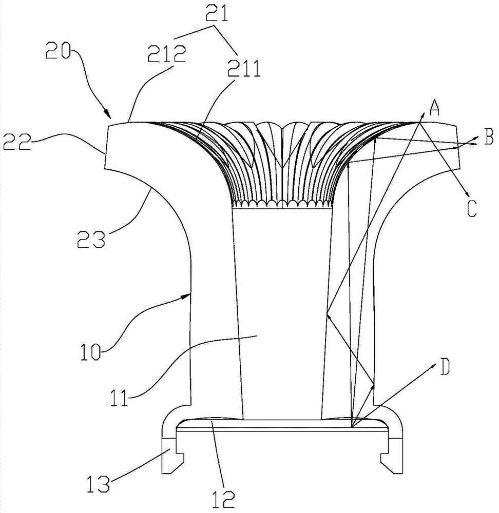
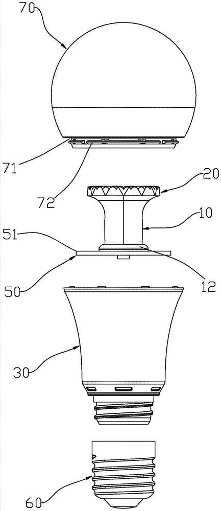
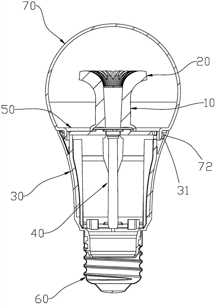
[0026] The light guide column of the present invention is used for distributing light emitted by a light source, and can be applied to a lamp to increase the light emitting angle of the lamp. Such as figure 1 As shown, it is a cross-sectional view of a light guide column according to an embodiment of the present invention. The light guide column includes a light guide column body 10 and a light exit portion 20. The middle part of the light guide column body 10 is provided with a bottom-up through hole 11, so that the light guide column body 10 is a hollow structure (such as figure 1 shown). The light exit part 20 is formed by bending and extending from the top of the light guide cylinder 10 to a direction away from th...


PUM


Abstract

The invention discloses a light guide column and a lamp. The light guide column comprises a light guide column body and a light outgoing portion, the middle of the light guide column body is provided with a through hole, the top of the light guide column body is bent in a direction away from the central axis of the light guide column body and extends to form the light outgoing portion, and the annular bottom of the light guide column body forms a light inlet portion. The light outgoing portion comprises an upper surface, lateral sides and a lower surface, the upper surface comprises arc portions facing reflection rays of the lower surface and the lateral sides, the lower surface is in a cambered structure facing recesses of the arc portions, and rays emitting to the lower surface are mostly refracted outwards by the lower surface. The light guide column has the advantages that the top of the light guide column body which is hollow is bent outwards and extends to form the light outgoing portion for light outgoing, the surfaces and the lateral sides of the light outgoing portion can all serve as light outgoing faces to enable a light source to emit light all around through the light outgoing portion, and consequently large-angle light outgoing can be realized, and high optical efficiency and simplicity in injection moulding are achieved. The lamp with the light guide column realizes large-angle uniform light outgoing.

Description

technical field [0001] The invention relates to a light guide column and a lamp, in particular to a light guide column capable of emitting light at a large angle and a lamp using the light guide column. Background technique [0002] LED light sources have been widely used due to their environmental protection, high efficiency and energy saving, and LED lamps gradually replace traditional lighting lamps. However, the light emitting angle of the current LED light source is relatively small, generally within 120 degrees. Therefore, compared with traditional incandescent lamps and halogen lamps, the light of LED lamps is more concentrated in the front, and the lateral illumination is uneven and the illumination space is smaller. [0003] In order to overcome the above-mentioned defects, in the related art, a light guide column is provided in the LED lamp, but the generally used light guide column is solid, and the designed LED lamp is limited by the inner light guide column, and...

Claims


Application Information

Patent Timeline
Patent Type & Authority Patents(China)
IPC IPC(8): G02B6/00F21V8/00F21K9/232F21K9/61F21V17/10F21Y115/10
Inventor 林祥华杨小明李江淮
Owner LEEDARSON IOT TECH INC
Why Eureka
Try Eureka