Energy storing device
An energy storage device and energy storage technology, applied in the fields of electric energy storage water heaters, energy storage air source water heaters, and energy storage heat exchangers, can solve the problems of poor utilization and small energy storage, and achieve simple structure and energy storage Large, well-designed effects
- Summary
- Abstract
- Description
- Claims
- Application Information
AI Technical Summary
Problems solved by technology
Method used
Image
Examples
Embodiment 1
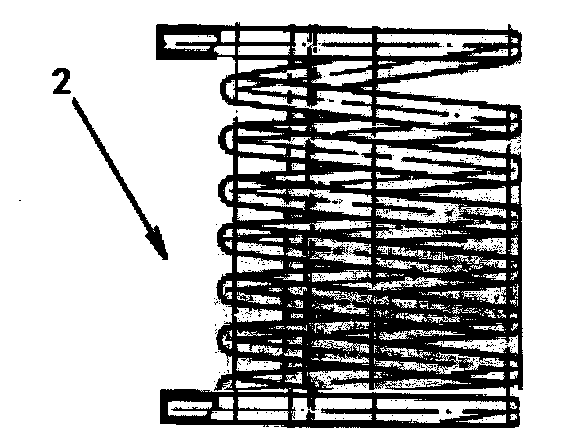
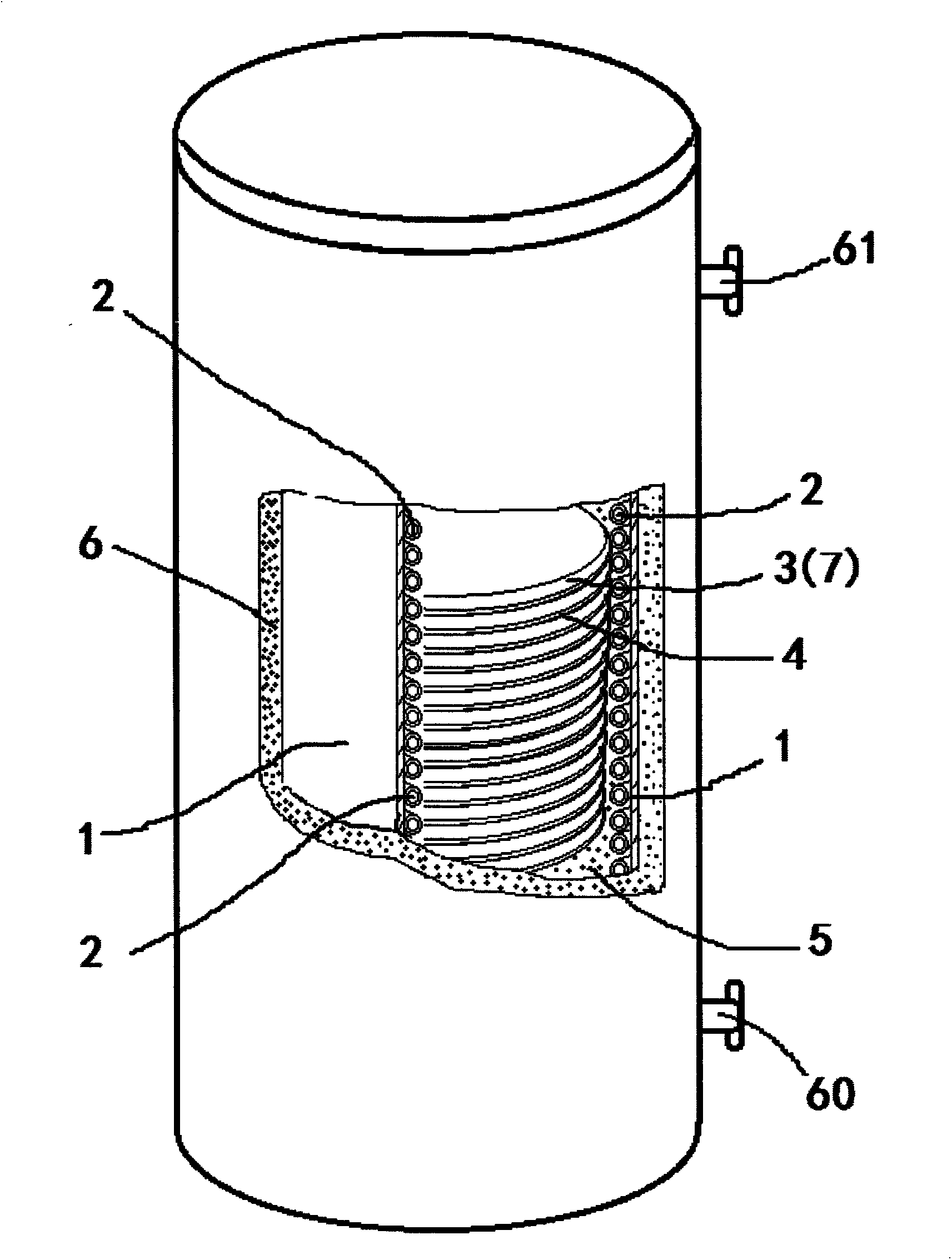
[0025] Such as figure 1 As shown, an energy storage device includes a container 1, a heat exchanger coil 2, an energy storage bag 3, a heat conductor 4, a heat transfer fluid 5, and a thermal insulation shell 6. The container 1 is provided with a heat exchanger coil 2, Several energy storage bags 3, heat conductors 4, and thermal fluid 5 between the heat exchanger coil 2, several energy storage bags 3 and heat conductors 4, the energy storage bags 3 are filled with phase change energy storage materials 7, and the container 1 is arranged in the thermal insulation shell 6, and the thermal insulation shell 6 is provided with a water inlet 60 and a water outlet 61, and the water inlet 60 and the water outlet 61 are respectively connected with the two ports of the heat exchanger coil 2.
[0026] In this embodiment, the container 1 is a cylindrical tank with a circular cross-section, the outer periphery of the heat exchanger coil 2 is close to the inner wall of the container 1, the ...
Embodiment 2
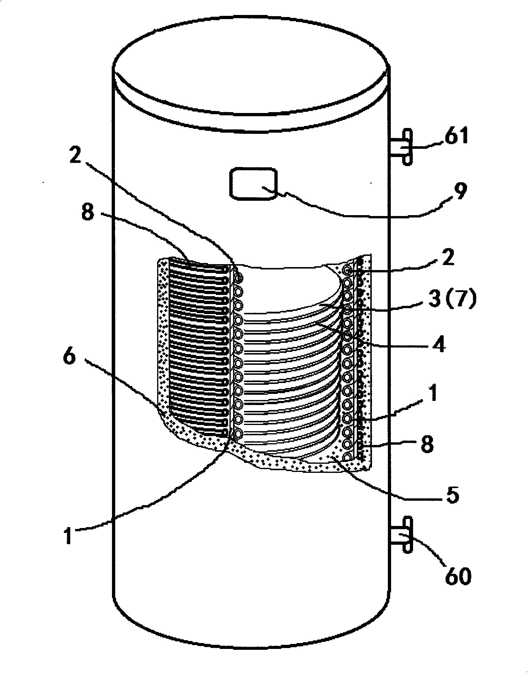
[0028] Such as figure 2 As shown, an energy storage device includes a container 1, a heat exchanger coil 2, an energy storage bag 3, a heat conductor 4, a heat transfer fluid 5, and a thermal insulation shell 6. The container 1 is provided with a heat exchanger coil 2, Several energy storage bags 3, heat conductors 4, and thermal fluid 5 between the heat exchanger coil 2, several energy storage bags 3 and heat conductors 4, the energy storage bags 3 are filled with phase change energy storage materials 7, and the container 1 is set in the thermal insulation shell 6, and the thermal insulation shell 6 is provided with a water inlet 60 and a water outlet 61, and the water inlet 60 and the water outlet 61 are respectively connected with the two ports of the heat exchanger coil 2,
[0029] Such as figure 2 As shown, the outer surface of the container 1 is wound with an electric heating element 8, and the electric heating element 8 is located between the container 1 and the ther...
Embodiment 3
[0032] Such as image 3 As shown, an energy storage device includes a container 1, a heat exchanger coil 2, an energy storage bag 3, a heat conductor 4, a heat transfer fluid 5, and a thermal insulation shell 6. The container 1 is provided with a heat exchanger coil 2, Several energy storage bags 3, heat conductors 4, and thermal fluid 5 between the heat exchanger coil 2, several energy storage bags 3 and heat conductors 4, the energy storage bags 3 are filled with phase change energy storage materials 7, and the container 1 is set in the thermal insulation shell 6, and the thermal insulation shell 6 is provided with a water inlet 60 and a water outlet 61, and the water inlet 60 and the water outlet 61 are respectively connected with the two ports of the heat exchanger coil 2,
[0033] Such as image 3 As shown, the outer surface of the container 1 is wound with a condenser 10, and the condenser 10 is arranged between the container 1 and the heat preservation shell 6. The hea...
PUM
| Property | Measurement | Unit |
|---|---|---|
| Thickness | aaaaa | aaaaa |
Abstract
Description
Claims
Application Information
 - R&D
- Intellectual Property
- Life Sciences
- Materials
- Tech Scout
- Unparalleled Data Quality
- Higher Quality Content
- 60% Fewer Hallucinations
Browse by: Latest US Patents, China's latest patents, Technical Efficacy Thesaurus, Application Domain, Technology Topic, Popular Technical Reports.
© 2025 PatSnap. All rights reserved.Legal|Privacy policy|Modern Slavery Act Transparency Statement|Sitemap|About US| Contact US: help@patsnap.com


