Ground wire

A technology of grounding wires and connectors, applied in the direction of needle point/slotted plate contacts used to penetrate insulating wires/cable core wires, multi-core cable end parts, etc. Electricity and other problems, to achieve the effect of simple operation, strengthen the clamping effect, and ensure the safety of personnel

Inactive Publication Date: 2014-09-10
STATE GRID SICHUAN ELECTRIC POWER
View PDF5 Cites 9 Cited by
  • Summary
  • Abstract
  • Description
  • Claims
  • Application Information

AI Technical Summary

Problems solved by technology

[0002] In the power outage maintenance work of distribution lines, a large number of 0.4kV insulated wires are used. Although the power has been cut off during the maintenance work, since the insulated wires cannot effectively realize the grounding of the line, there may be a reverse power transmission situation. Risks to personal safety of personnel

Method used


Image

  • Ground wire
  • Ground wire

Examples


Embodiment 1

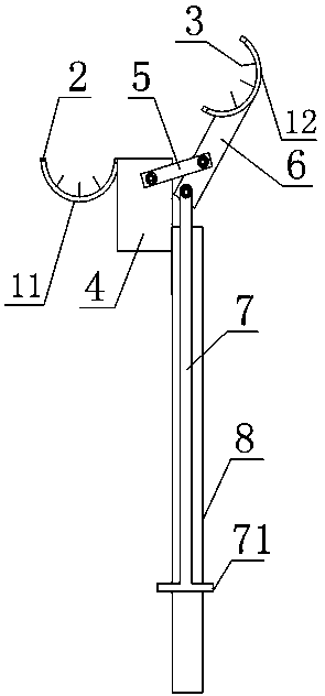
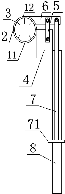
[0020] Such as figure 1 with figure 2 The shown grounding wire includes a fixed clamp block 11 and a movable clamp block 12 matched with the fixed clamp block 11, the fixed clamp block 11 and the movable clamp block 12 are provided with grooves, the fixed clamp block 11 A magnetic block 2 is arranged on the edge of the groove of the clamp block 11 and the movable clamp block 12, and a puncture needle 3 is arranged in the groove, and the fixed clamp block 11 is fixed on the fixed block 4, and the fixed block 4 is fixed with an operating rod 8, and the operating rod 8 is provided with a moving rod 7. The movable clamping block 12 is movably connected to the moving rod 7 through the connecting piece 6. The connecting piece 6 and the fixed block 4 A connecting rod 5 is movably connected between them, and a ground wire connecting device is arranged on the fixed block 4 or the fixed clamp block 11 .

[0021] In this embodiment, under the movement of the moving rod 7, the movable ...

Embodiment 2

[0024] Such as figure 1 with figure 2 The grounding wire shown in this embodiment is based on Embodiment 1. In order to facilitate the operation of the moving rod, the bottom of the moving rod 7 is fixed with an operating handle 71, and the operating rod 8 is provided with The chute, the operating handle 71 is located in the chute. The chute limits the moving position of the moving rod, so that the structure is stable during its operation.

Embodiment 3

[0026] Such as figure 1 with figure 2 Shown is a grounding wire. In this embodiment, on the basis of the above embodiments, at least two puncture needles 3 are respectively arranged in the grooves of the fixed clamping block 11 and the movable clamping block 12 .

[0027] The lengths of the puncture needles 3 are equal.

[0028] The puncture is aimed at the insulation layer of the cable. When the number of puncture needles is too small, that is, when there is only one on the fixed clamp block 11 and the movable clamp block 12, the cable is easy to move when the cable is punctured. When two puncture needles are used, the cables are placed on the two puncture needles, which will not move, so that the puncture is convenient for puncturing the cables. The lengths of the puncture needles 3 are equal, so that the depths of the puncture needles piercing into the cables are consistent, further ensuring the reliability of the grounding.


PUM


Abstract

The invention discloses a ground wire. The ground wire comprises a fixed clamp block and a movable clamp block matched with the fixed clamp block, a groove is formed in each of the fixed clamp block and the movable clamp block, a magnetic block is arranged on the edge of the groove of each of the fixed clamp block and the movable clamp block, a puncture needle is arranged in each groove, the fixed clamp block is fixed on a fixed block, the fixed block is fixed with an operating rod, a movable rod is arranged in the operating rod, the movable clamp block is movably connected with the movable rod through a connecting piece, a connecting rod is movably connected between the connecting piece and the fixed block, and the fixed block or the fixed clamp block is provided with a ground wire connecting device. The ground wire has advantages that an insulating wire is punctured to ground reliably, and the operation is easy to perform.

Description

technical field [0001] The invention relates to a grounding wire used for electric leakage in electric power construction, in particular to a grounding wire. Background technique [0002] In the power outage maintenance work of distribution lines, a large number of 0.4kV insulated wires are used. Although the power has been cut off during the maintenance work, since the insulated wires cannot effectively realize the grounding of the line, there may be reverse power transmission, which will affect the maintenance. The personal safety of personnel poses hidden dangers. Contents of the invention [0003] The technical problem to be solved by the present invention is to provide a piercing type grounding wire which can be reliably grounded by piercing the insulated wire and is easy to operate. [0004] The technical solution adopted by the present invention to solve the above problems is: [0005] A grounding wire, comprising a fixed clamp block and a movable clamp block matc...

Claims


Application Information

Patent Timeline
Patent Type & Authority Applications(China)
IPC IPC(8): H01R11/11H01R4/24
Inventor 刘俊万体勇
Owner STATE GRID SICHUAN ELECTRIC POWER
Why Eureka
Try Eureka