Novel ground wire clamp

A grounding wire clamp, a new type of technology, is applied in the direction of winding connectors, clips connecting conductors, switching devices, etc. It can solve the problems of difficult grounding wires, difficult grounding, and poor grounding contact area, so as to ensure safe operation, Convenient grounding method and reliable grounding effect

Pending Publication Date: 2018-02-02
HUIZHOU POWER SUPPLY BUREAU OF GUANGDONG POWER GRID CO LTD
View PDF0 Cites 8 Cited by
  • Summary
  • Abstract
  • Description
  • Claims
  • Application Information

AI Technical Summary

Problems solved by technology

This regulation makes a large number of line voltage transformers and other equipment with outgoing line intervals lack grounding switches. With the existing grounding line structure, it is necessary to use an aerial work vehicle to lift people to the same level as the line before they can be connected.
At the same time, in some areas of the substation, it is difficult for operating vehicles to enter, so it is very difficult to connect the grounding wire, which has caused problems in the application of the grounding wire
[0004] At present, the grounding wires used in substations are all connected in a straight line between the grounding clamp and the operating rod, and the conductors suitable for grounding are arranged horizontally and horizontally. However, most equipment such as CVT directly lead vertically from the terminal board to the frame jumper above. The traditional grounding wire will increase the difficulty for the operator to hang the wire, and the wire clip becomes a horizontal snap-in method, making the grounding difficult to stabilize. At the same time, the grounding contact area is poor, which seriously affects the grounding quality

Method used


Image

  • Novel ground wire clamp
  • Novel ground wire clamp
  • Novel ground wire clamp

Examples


Embodiment 1

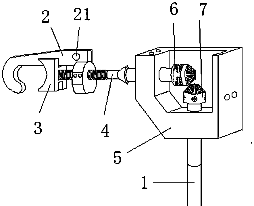
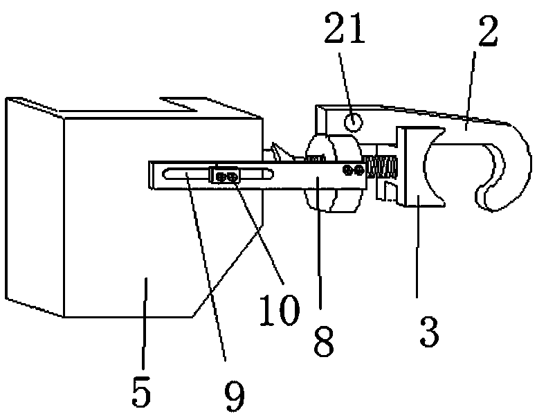
[0022] like figure 1 and figure 2 As shown, a new type of grounding wire clamp, wherein the grounding wire clamp includes a clamping part, a connecting part, and an operating rod 1. The clamping part is connected with the operating rod 1 through the connecting part to form an L-shaped structure. The connection between the connecting part and the clamping part The clamping part is provided with a hook clip 2 and a push clip, and the hook clip 2 is provided with a wiring hole 21. The hook clip 2 is slidably connected with the push clip, one end of the push clip is movably connected with the connection part, and the other end of the push clip One end is slidingly connected with the hook clip 2, one end of the limit mechanism is fixedly connected with the hook clip 2, the other end of the limit mechanism is movably connected with the connection part, and the connection part is movably connected with the operating rod 1.

[0023] Wherein, the hook clip 2 is a curved hook body str...

Embodiment 2

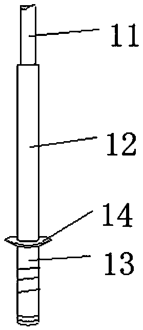
[0028] like image 3 As shown, the difference between this embodiment and Embodiment 1 is that the operating rod 1 is provided with an insulating part 11 and a metal part 12, the metal part 12 is connected to the connecting part, and the metal part 11 is connected to the insulating part 12 through bolts. The insulating part 12 is provided with an operating handle 13 at the end away from the metal part, and the operating handle 13 is provided with a guard ring 14 and an anti-slip thread.

[0029] The insulating part 12 of the operating rod 1 is made of plastic material, which plays a main insulating role, and has a long length to ensure the safe operation of the operator; the operating handle 13 is convenient for the operator to rotate the operating rod 1 when using the grounding clamp for wiring; the protective ring 14 In order to prevent the operator from extending his hand to the connecting part when the operating lever 1 is rotated, thereby causing electric shock; the anti-...


PUM


Abstract

The invention belongs to the technical field of power detection and particularly relates to a novel ground wire clamp which comprises a clamping part, a connecting part and an operating rod. The clamping part is connected to the operating rod through the connecting part to form an L-shaped structure. A limit mechanism is arranged between the connecting part and the clamping part. The clamping partis provided with a hook clamp and a pushing clamp. The hook clamp is provided with a wiring hole and is slidingly connected to the pushing clamp. One end of the pushing clamping is movably connectedto the connecting part. The other end of the pushing clamp is slidingly connected to the hook. One end of the limit mechanism is fixedly connected to the hook, and the other end of the limit mechanismis movably connected to the connecting part. The connecting part is movably connected to the operating rod. According to the novel ground wire clamp, through the principle of a rotating shaft of a helical gear, a wiring clamp and a manual rotation operation rod are separated to form a core component which is an L-shaped operation mechanism, and a convenient grounding mode of a lead conductor in avertical direction is realized.

Description

technical field [0001] The invention belongs to the technical field of electric power detection, and in particular relates to a novel grounding clamp. Background technique [0002] The grounding wire is a necessary safety tool in substation power outage maintenance work, which involves the personal safety of equipment maintenance staff and is very important. When the equipment is converted to maintenance after power failure, some equipment does not have a grounding switch device on both sides or one side. At this time, it is necessary to manually use an external grounding wire to hang on the associated conductor of the primary equipment. Grounded to complete the state of equipment maintenance. The grounding method of connecting the grounding wire and the conductor can not only allow the residual current of the equipment shell or the primary conductor to be released to the ground, but also avoid the induction potential caused by the induction effect during the power failure ...

Claims


Application Information

Patent Timeline
Patent Type & Authority Applications(China)
IPC IPC(8): H02B3/00H01R11/15H01R43/027
CPCH02B3/00H01R11/15H01R43/027
Inventor 黎舟洋陈锦鹏王铁柱高士森黄志罗斐李冠桥卓定明赖昱光叶欢欢晏结钰王博李柯睿
Owner HUIZHOU POWER SUPPLY BUREAU OF GUANGDONG POWER GRID CO LTD
Why Eureka
Try Eureka