Earth terminal fitting and electric connector having the same

A technology of electrical connectors and grounding terminals, applied in the direction of connection, contact parts, electrical components, etc., can solve problems such as difficult maintenance and non-contact status, and achieve the effects of improving reliability, preventing damage, and improving reliability

Inactive Publication Date: 2006-07-26
JST MFG CO LTD
View PDF0 Cites 9 Cited by
  • Summary
  • Abstract
  • Description
  • Claims
  • Application Information

AI Technical Summary

Problems solved by technology

Therefore, even when the second contact member and the grounded housing are in the

Method used


Image

  • Earth terminal fitting and electric connector having the same
  • Earth terminal fitting and electric connector having the same
  • Earth terminal fitting and electric connector having the same

Examples


Embodiment Construction

[0031] Preferred embodiments of the present invention will be described below.

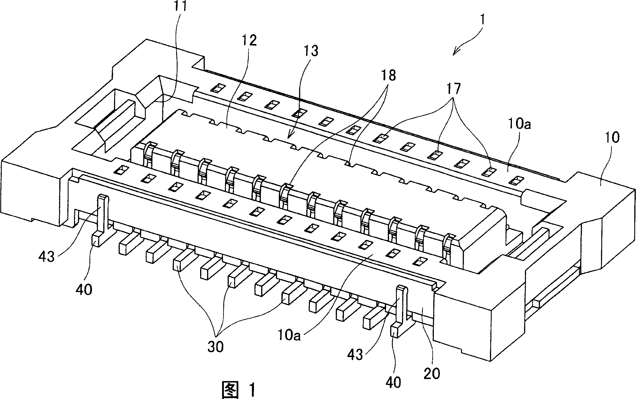
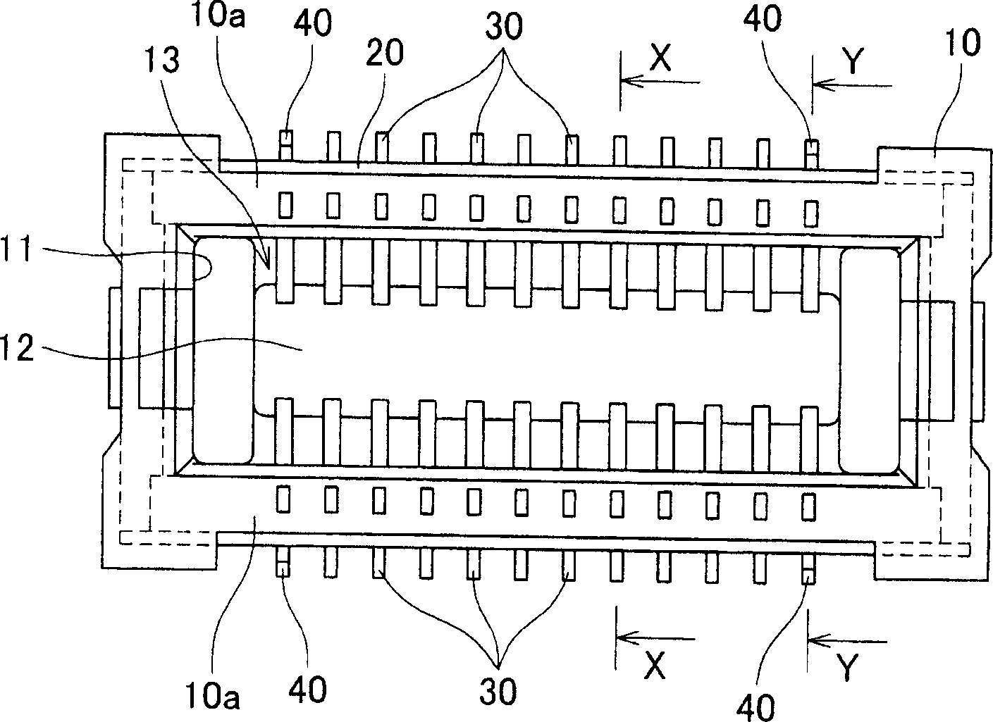
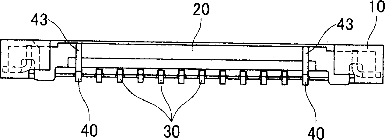
[0032] FIG. 1 is a perspective view of a socket connector according to an embodiment of the present invention. Fig. 2 is the view of the structure of the receptacle connector shown in Fig. 1, wherein Figure 2A for the floor plan, Figure 2B is the front view, Figure 2C with 2D respectively along Figure 2A Cross-sectional view on lines X-X and Y-Y.

[0033] The socket connector 1 shown in FIG. 1 includes a body 10 , a socket housing 20 , a socket contact portion 30 and a socket ground contact portion 40 . The socket connector 1 is a thin connector with a height of about 1 mm. Since very thin housings can be constructed in accordance with the present invention, it is more useful when applied to the very thin connectors described above.

[0034] The body 10 is a member made of insulating resin and has a substantially rectangular parallelepiped shape. As shown in FIGS. 1 and 2A, the center of...


PUM


Abstract

Disclosed is an electric connector having improved reliability and capable of being easily identified. A receptacle connector comprises a housing 10 insert-molded so that a receptacle shell 20 is embedded therein. The receptacle connector comprises a receptacle contact 30 and a receptacle earth contact 40. The receptacle earth contact 40 comprises a shell contacting part contacted to an outer circumference of the receptacle shell 20 and capable of being visible from an exterior of the receptacle connector 1.

Description

technical field [0001] The present invention relates to an electrical connector for electrically connecting a plurality of substrates and the like. Background technique [0002] Generally, electric devices such as cellular phones are provided with a plurality of substrates. In order to transmit and receive a plurality of signals between the substrates, it is necessary to electrically connect the substrates to each other. When electrically connecting these substrates, for example, a board-to-board type connector assembly is often used, which includes mating plug connectors and receptacle connectors. That is, in this case, when the board on which the plug connector is fixed and the board on which the receptacle connector is fixed are connected together, the plug connector and the receptacle connector are mated to each other so that the plurality of boards are electrically connected. . [0003] If external noise enters the connector, it may cause the above connector assembly...

Claims


Application Information

Patent Timeline
IPC IPC(8): H01R13/648H01R4/66
CPCH01R12/716H01R13/6597H01R13/6594H01R13/41H01R13/24H01R13/658H01R13/6583H01R13/20
Inventor 知览清彦恩地晓彦樫尾正行
Owner JST MFG CO LTD
Why Eureka
Try Eureka