Inductor type rotary motor
A technology of rotating electrical machines and rotors, applied in the field of induction rotating electrical machines, which can solve the problems of small torque per unit size, small amount of permanent magnets used, and limited application range, so as to increase torque, reduce the amount of permanent magnets used, and expand the application range effect
- Summary
- Abstract
- Description
- Claims
- Application Information
AI Technical Summary
Problems solved by technology
Method used
Image
Examples
Embodiment approach 1
[0054]
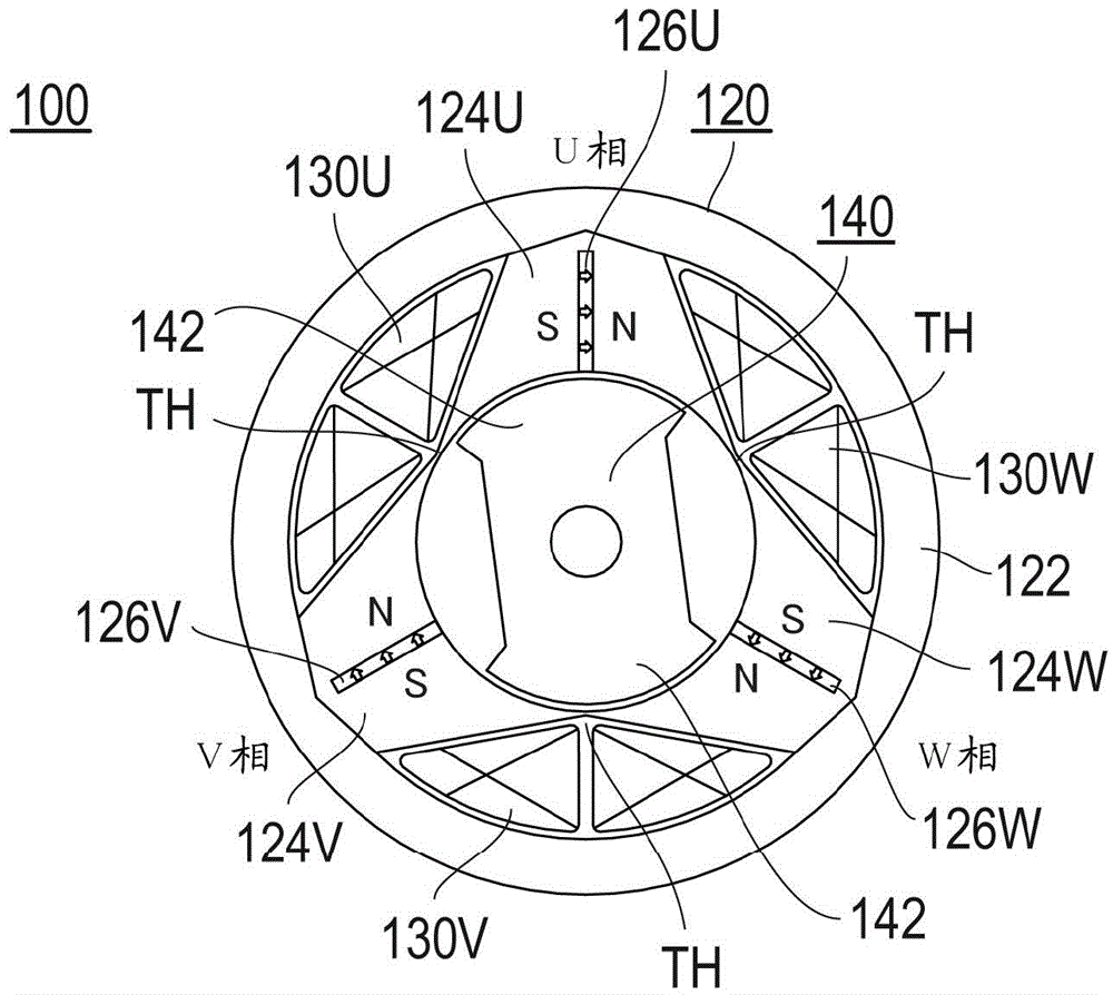
[0055] figure 1 It is a block diagram of the induction-type rotating electric machine of Embodiment 1. As shown in the figure, the induction rotating electric machine 100 of this embodiment has a stator 120 and a rotor 140 .
[0056] Stator 120 has cylindrical yoke 122 , U-phase teeth 124U, V-phase teeth 124V, and W-phase teeth 124W. The U-phase teeth 124U, the V-phase teeth 124V, and the W-phase teeth 124W are respectively circumferentially arranged on the inner peripheral side of the yoke 122 at equiangular central angles of 120°. The induction-type rotating electric machine 100 of Embodiment 1 is a three-phase induction-type rotating electric machine.
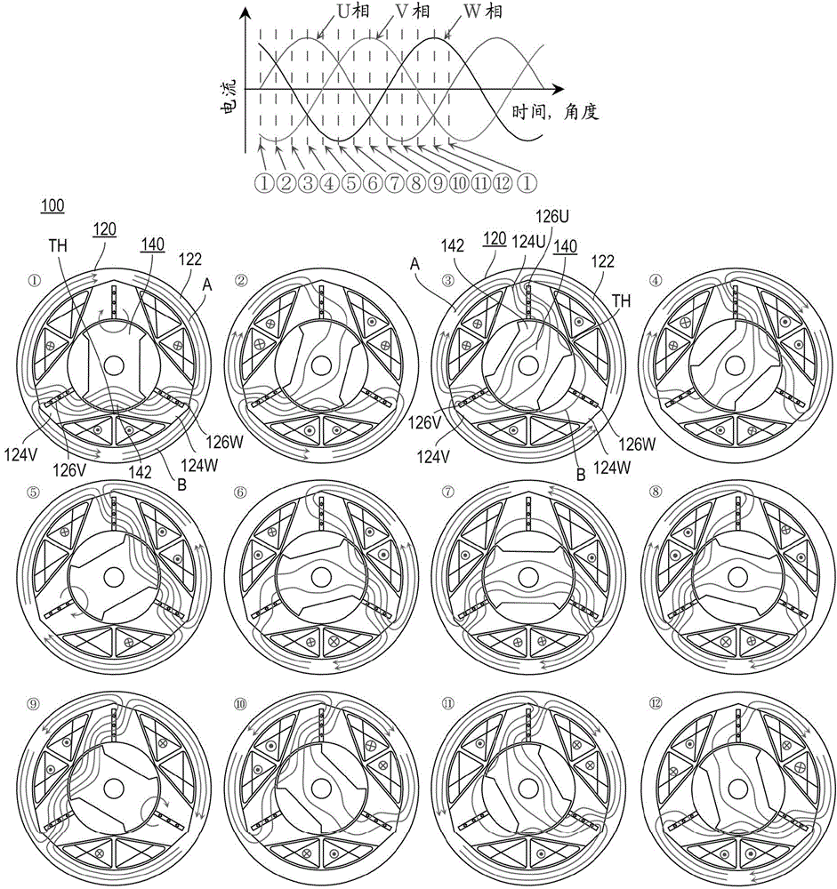
[0057] Respectively, permanent magnets 126U are arranged on the U-phase teeth 124U, permanent magnets 126V are arranged on the V-phase teeth 124V, and permanent magnets 126W are arranged on the W-phase teeth 124W. In the induction rotating electrical machine 100 according to Embodiment 1, one permanent magnet i...
Embodiment approach 2
[0070]
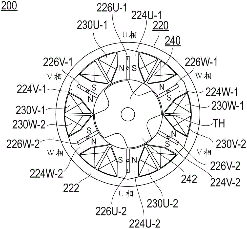
[0071] image 3 It is a block diagram of the induction type rotating electric machine of Embodiment 2. As shown in the figure, the induction rotating electric machine 200 of this embodiment has a stator 220 and a rotor 240 .
[0072] The stator 220 has a cylindrical yoke 222 , U-phase teeth 224U- 1 , 224U- 2 , V-phase teeth 224V- 1 , 224V- 2 , and W-phase teeth 224W- 1 , 224W- 2 . U-phase teeth 224U-1, 224U-2, V-phase teeth 224V-1, 224V-2, and W-phase teeth 224W-1, 224W-2 are arranged on the inner peripheral side of the yoke 222 at equiangular central angles of 60°. . The induction-type rotating electrical machine 200 of Embodiment 2 is a 6-tooth three-phase induction-type rotating electrical machine.
[0073] Permanent magnet 226U- 1 is arranged on U-phase tooth 224U- 1 , permanent magnet 226V- 1 is arranged on V-phase tooth 224V- 1 , and permanent magnet 226W- 1 is arranged on W-phase tooth 224W- 1 , respectively. Also, permanent magnet 226U- 2 is arranged on ...
Embodiment approach 3
[0092]
[0093] Figure 8 It is a block diagram of the induction type rotating electric machine of Embodiment 3. As shown in the figure, the induction rotating electrical machine 300 of this embodiment has a stator 320 and a rotor 340 .
[0094] The stator 320 has a cylindrical yoke 322 , U-phase teeth 324U- 1 , 324U- 2 , V-phase teeth 324V- 1 , 324V- 2 , and W-phase teeth 324W- 1 , 324W- 2 . U-phase teeth 324U-1, 324U-2, V-phase teeth 324V-1, 324V-2, W-phase teeth 324W-1, 324W-2 are respectively arranged on the inner periphery of the yoke 322 at equiangular central angles of 60° side. The induction-type rotating electrical machine 300 of the third embodiment is the same as the induction-type rotating electrical machine 200 of the second embodiment, and is a six-tooth three-phase induction-type rotating electrical machine.
[0095] Respectively, two permanent magnets 326U-1A and 326U-1B are arranged on the U-phase tooth 324U-1, two permanent magnets 326V-1A and 326V-1B ar...
PUM
 Abstract
Description
Claims
Application Information
 - R&D
- Intellectual Property
- Life Sciences
- Materials
- Tech Scout
- Unparalleled Data Quality
- Higher Quality Content
- 60% Fewer Hallucinations
Browse by: Latest US Patents, China's latest patents, Technical Efficacy Thesaurus, Application Domain, Technology Topic, Popular Technical Reports.
© 2025 PatSnap. All rights reserved.Legal|Privacy policy|Modern Slavery Act Transparency Statement|Sitemap|About US| Contact US: help@patsnap.com


