Flat plate type photocatalytic reaction device

A photocatalytic reaction and flat-plate technology, applied in chemical instruments and methods, dispersed particle separation, separation methods, etc., to achieve the effects of increasing residence time, improving satisfaction and happiness, and high economic and social value

Inactive Publication Date: 2014-09-17
SHANGHAI UNIVERSITY OF ELECTRIC POWER
View PDF11 Cites 3 Cited by
  • Summary
  • Abstract
  • Description
  • Claims
  • Application Information

AI Technical Summary

Problems solved by technology

[0016] Aiming at the urgent technical problems to be solved in the current photocatalytic air purifier, the present invention provides a flat photocatalytic r...

Method used


Image

  • Flat plate type photocatalytic reaction device
  • Flat plate type photocatalytic reaction device
  • Flat plate type photocatalytic reaction device

Examples


Embodiment Construction

[0029] The present invention will be further described below in conjunction with the drawings and embodiments.

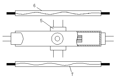
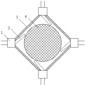
[0030] Such as figure 1 , As shown in 2, a flat-plate photocatalytic reaction device includes an airflow injection port 2, a reactor cavity 3, and a photocatalytic film 4.

[0031] The reactor cavity 3 is a quadrilateral cavity. The four corners of the quadrilateral cavity are provided with air inlets 1 respectively. The photocatalytic film 4 is installed in the middle of the reactor cavity 3, and the air inlet 1 and the photocatalytic film 4 are An airflow injection port 2 is arranged in between. One end of the airflow injection port 2 is connected with the air inlet 1 and the other end is tangentially connected with the outer circle of the photocatalytic film 4. The front and rear ends of the reactor cavity 3 are respectively provided with air outlets 5.

[0032] Such as figure 1 As shown, an ultraviolet lamp tube 6 and a fluorescent tube 7 are respectively arranged abov...


PUM


Abstract

The invention relates to a flat plate type photocatalytic reaction device. The reactor cavity is a quadrilateral cavity, four corners of which are respectively provided with an air inlet. The reactor cavity is internally provided with a photocatalytic film in the middle, and airflow jet orifices are arranged between the air inlets and the photocatalytic film. One ends of the airflow jet orifices are connected to the air inlets, and the other ends are in tangent connection with the outer circle of the photocatalytic film. The upper end and the lower end of the reactor cavity are respectively provided with an air outlet. With the advantages of reasonable design, simple structure and convenient operation, the flat plate type photocatalytic reaction device provided by the invention has wide market prospects and high social and economic value.

Description

Technical field [0001] The invention relates to a photocatalytic air purifier, in particular to a plate-type photocatalytic air purification reaction device with high efficiency and low consumption. Background technique [0002] At present, photocatalytic air purifiers and photocatalytic gas purification reactors on the market have various structures, and the most researched is the cylindrical air flow channel. The flat plate reactor is a new type of photocatalytic gas purification reactor. Among the related air purifiers Few reactors adopt this design. [0003] Currently published patents: [0004] 1. The three-dimensional photocatalytic air purifier invented by Chen Hanyu, Henan Urban Construction College, patent number: 201310584299.5. [0005] 2. Photocatalytic air purifier invented by Chen Dawei, Anshan City, Liaoning Province, Patent No.: 200410087631.8 [0006] 3. The circulating air purifier invented by Qiao Jingfei in Dongcheng District, Beijing, patent number: 201310...

Claims


Application Information

Patent Timeline
IPC IPC(8): B01D53/86B01D53/64
Inventor 吴江李忺胡程镇袁斌霞吴强陶莉莉蔡雁南翟天利唐鹏飞陆金勇
Owner SHANGHAI UNIVERSITY OF ELECTRIC POWER
Why Eureka
Try Eureka