Eureka AIR delivers breakthrough ideas for toughest innovation challenges, trusted by R&D personnel around the world.

Die for machining thin-walled door-shaped bent part and use method of die

A technology of bending parts and door shape, which is applied in the field of machinery, can solve the problems of high manufacturing cost and inability to adjust the bending position, and achieve the effect of convenient operation and compact mold structure

Active Publication Date: 2014-09-17
CHINA HANGFA SOUTH IND CO LTD
View PDF6 Cites 5 Cited by
  • Summary
  • Abstract
  • Description
  • Claims
  • Application Information

AI Technical Summary

Problems solved by technology

[0009] One needs to manufacture multiple sets of molds, and the manufacturing cost is high;
[0010] 2. Each set of molds only completes one bending action, that is, the quick-change punch can only bend one angle each time, which is only suitable for single-piece or very small batch processing;
[0011] The position of the three molds is fixed after manufacturing, and the bending position cannot be adjusted

Method used


Image

  • Die for machining thin-walled door-shaped bent part and use method of die
  • Die for machining thin-walled door-shaped bent part and use method of die
  • Die for machining thin-walled door-shaped bent part and use method of die

Examples


Embodiment Construction

[0034] In order to have a clearer understanding of the technical features, purposes and effects of the present invention, the specific implementation manners of the present invention will now be described with reference to the accompanying drawings. Wherein, the same parts adopt the same reference numerals.

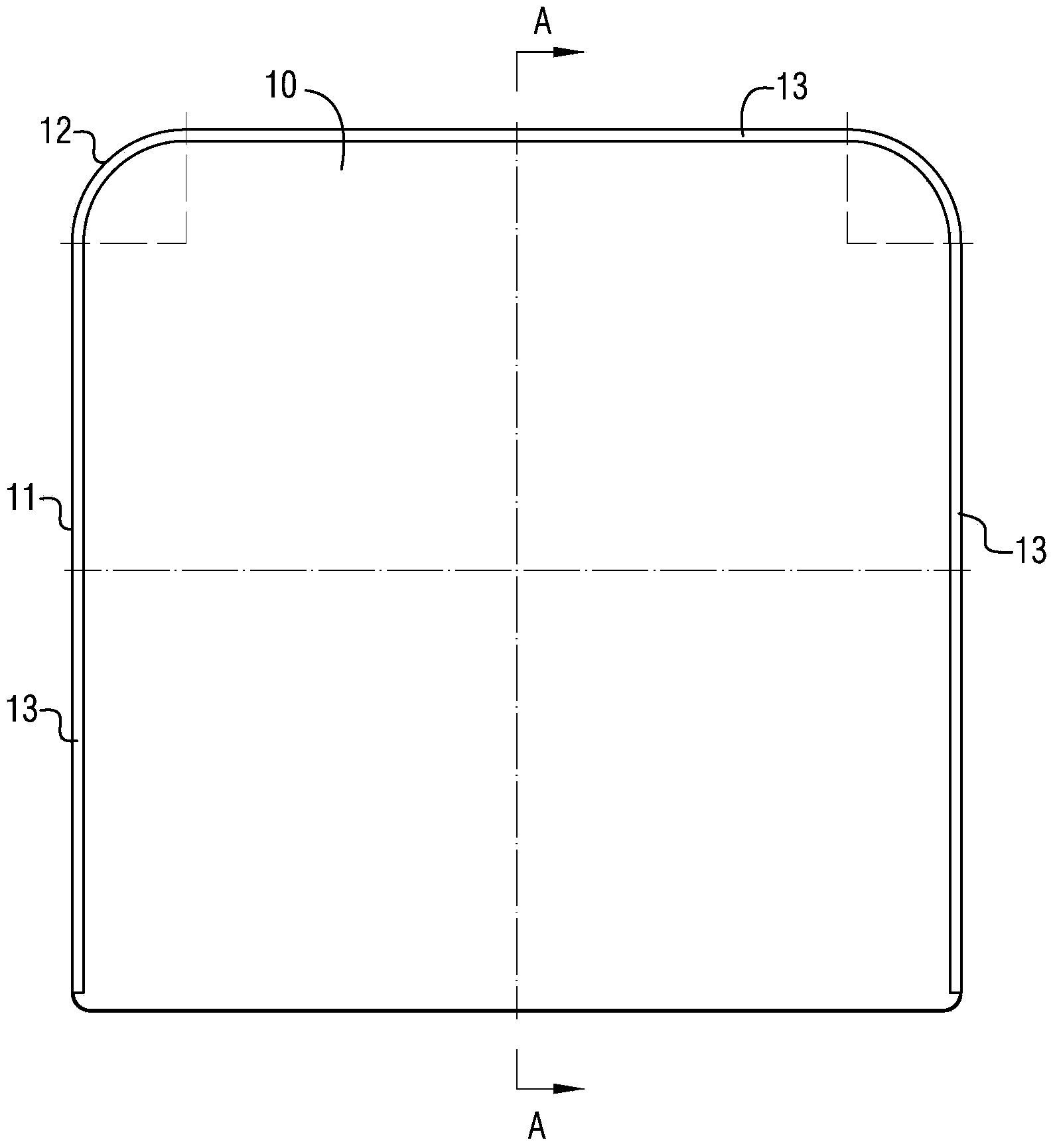
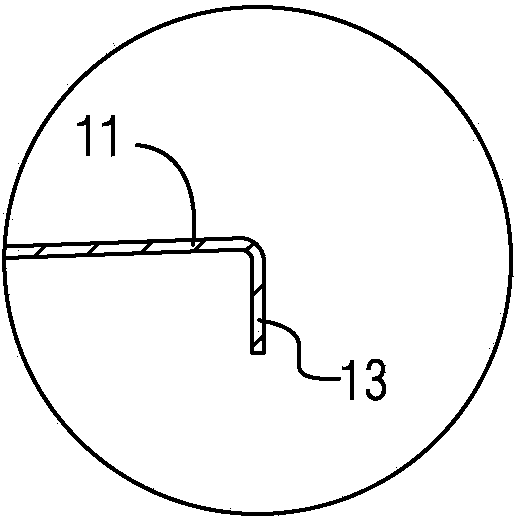
[0035] Figure 1a is a structural schematic diagram of a thin-walled door-shaped bending part; Figure 1b for Figure 1a Schematic diagram of the A-A section structure in the middle; Figure 1c for Figure 1b The enlarged schematic diagram of the structure at B; figure 2 It is a schematic diagram of a working state sectional structure of a mold for processing thin-walled door-shaped bending parts according to a specific embodiment of the present invention; Figure 3a for figure 2 The schematic diagram of the cross-sectional structure of the binder plate shown; Figure 3b for figure 2 The schematic diagram of the cross-sectional structure of the female mold shown;...


PUM


Abstract

The invention provides a die for machining a thin-walled door-shaped bent part. The die comprises an upper template and a lower template, wherein the upper template is provided with a material pressing plate; the material pressing plate is connected with the upper template by a compression spring; an inclined block is arranged outside the material pressing plate; a female die is arranged on the lower template; the female die is slidably connected with the lower template by a first reset device; a cone block is arranged at the top of an ejector and is slidably connected with the female die; the outside of the female die is provided with a slide seat slidably connected with the lower template by a second reset device; the slide seat is fixedly connected with a punch and is slidably connected with the inclined block. The invention also provides a use method of the die. According to the die for machining the thin-walled door-shaped bent part and the use method of the die, the die is compact in structure and convenient to operate, and the production efficiency is greatly improved.

Description

technical field [0001] The invention relates to the field of machinery, in particular to a mold for processing thin-walled door-shaped bending parts and a use method thereof. Background technique [0002] In the mechanical field, especially in the aerospace field, a large number of thin-walled parts are used, including thin-walled door bends, which include a top surface at an angle of 90° to the top surface The bottom of at least one of the side parts is provided with an inwardly bent bending part at an angle of 90° to the side part. The overall shape of the part is like the word "door", and the wall thickness is generally 0.3-0.8 mm. [0003] Figure 1a is a structural schematic diagram of a thin-walled door-shaped bending part; Figure 1b for Figure 1a Schematic diagram of the A-A section structure in the middle; Figure 1c for Figure 1b The enlarged schematic diagram of the structure in B. see Figure 1a-1c As shown, the thin-walled door-shaped bending part includ...

Claims


Application Information

Patent Timeline
Patent Type & Authority Applications(China)
IPC IPC(8): B21D37/10B21D5/06
Inventor 何旺君范雪莉聂慧萍袁良清黎承东
Owner CHINA HANGFA SOUTH IND CO LTD
Why Eureka
Eureka Blog
Learn More