Fluid dynamic machine with rotating wheel piston speed change mechanism

A speed change mechanism and fluid power technology, applied in the direction of rotary piston machines, rotary piston engines, rotary or swinging piston engines, etc., can solve problems affecting the structural performance of piston compressors and piston engines

Inactive Publication Date: 2014-09-17
周觉明
View PDF0 Cites 11 Cited by
  • Summary
  • Abstract
  • Description
  • Claims
  • Application Information

AI Technical Summary

Problems solved by technology

[0002] The currently used piston compressors and piston engines use a piston crankshaft connecting rod mechanism. The piston crankshaft connecting rod mechanism becomes the reciprocating motion of the piston through the rotation of the crankshaft; The back pressure of the pist

Method used


Image

  • Fluid dynamic machine with rotating wheel piston speed change mechanism
  • Fluid dynamic machine with rotating wheel piston speed change mechanism
  • Fluid dynamic machine with rotating wheel piston speed change mechanism

Examples


Embodiment Construction

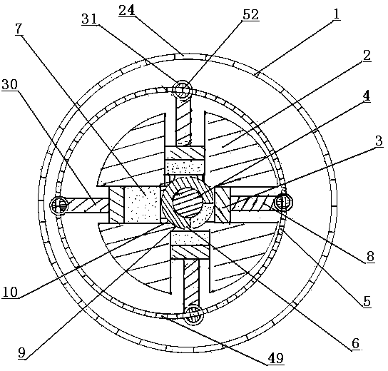
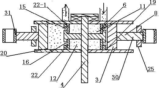
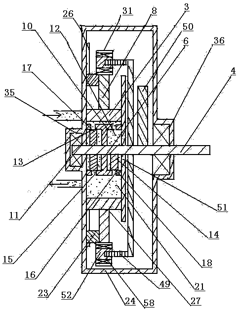
[0034] A rotary-piston mechanism 1 for a hydrodynamic machine with a rotary-piston mechanism, such as figure 1 As shown, it is composed of cylinder block 2, piston 3, sliding connecting rod 8, transmission shaft 4, wheel transmission device 5 and gas distribution device 6; cylinder block 2 is composed of annular combined cylinder head 9 and one or more than one cylinder 7 The cylinder head 10 of the cylinder 7 and the annular combined cylinder head 9 is fixedly installed with each other, and the cylinder 7 is distributed outwards with the center of the annular combined cylinder head 9 . Such as image 3 As shown, there is an air intake chamber 11 and an exhaust chamber 12 inside the annular combined cylinder head 9; the transmission shaft 4 passes through the center of the annular combined cylinder head 9, and the transmission shaft 4 is installed on the upper bearing seats on both sides of the body 24 35 and the bearing support rotation in the lower bearing block 36. Such a...


PUM


Abstract

The invention discloses a fluid dynamic machine with a rotary wheel piston speed change mechanism. The fluid dynamic machine is composed of a cylinder body (2), a piston (3), a sliding connecting rod (8), a transmission shaft (4), a rotary wheel transmission device (5) and an air distribution device (6), wherein a rotary wheel disc (51 )of the rotary wheel transmission device (5) of the rotary wheel piston speed change mechanism (1) is eccentrically arranged on the shaft body of the transmission shaft (4); a guide shaft (52) on the rotary wheel disc (51) and the sliding connecting rod (8) are linked with each other; the rotary wheel disc (51) rotates eccentrically; a piston (3) does decelerated motion along with the length change of the arm of force between the axis of the guide shaft (52) and that of the transmission shaft (4); under the driving of the sliding connecting rod (8), the piston (3) performs decelerated motion from a lower stop point (20) to an upper stop point (19) and performs accelerated motion from the upper stop point (19) to the lower stop point(20).

Description

technical field [0001] The invention relates to a piston-type runner-piston speed change mechanism for fluid machinery and engines, and relates to the technical field of fluid power machinery manufacturing such as pumps, hydraulic motors, air motors, compressors, expansion power machines and engines. Background technique [0002] The currently used piston compressors and piston engines use a piston crankshaft connecting rod mechanism. The piston crankshaft connecting rod mechanism becomes the reciprocating motion of the piston through the rotation of the crankshaft; The back pressure of the piston is not directly proportional. The above defects are unavoidable for the piston crankshaft and connecting rod mechanism. This defect seriously affects the structural performance of the piston compressor and the piston engine. Replace the existing piston crankshaft connecting rod mechanism. Contents of the invention [0003] The purpose of the present invention is to provide a vol...

Claims


Application Information

Patent Timeline
IPC IPC(8): F01C1/00F01C3/00F04C2/00F04C3/00F02B53/00F02B55/00
CPCY02T10/17Y02T10/12
Inventor 周觉明
Owner 周觉明
Why Eureka
Try Eureka