

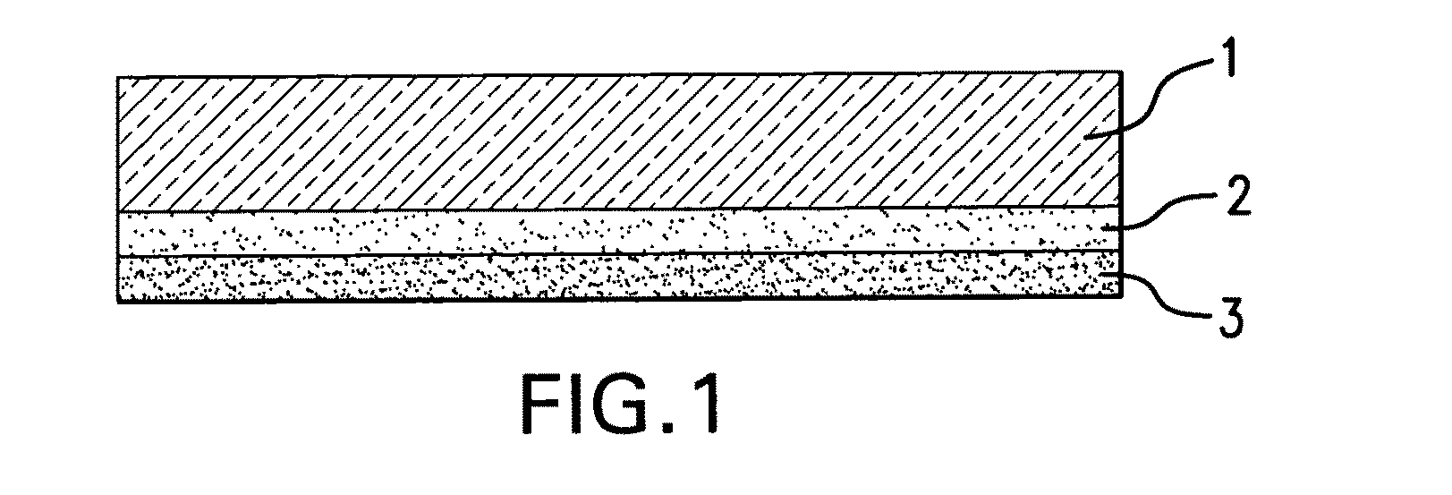
Scratch-resistant silicone coating for cooktops made of glass or glass ceramic
a technology of glass or glass ceramic and scratch-resistant silicone, which is applied in the direction of coatings, layered products, transportation and packaging, etc., can solve the problems of significantly reducing the strength of the glass layer underneath, and achieve the effect of not reducing the strength of the substrate and high storage stability
- Summary
- Abstract
- Description
- Claims
- Application Information
AI Technical Summary
Benefits of technology
Problems solved by technology
Method used
Image

Examples
example 1
Counter-Example 1
Single-Layer Light Gray Silicone Coating with Low Scratch Resistance
[0088]A colorless glass ceramic plate, approximately 60 cm wide, 80 cm long, and 4 mm thick, smooth on both sides and with the composition according to European Patent Reference EP 1 837 314 A1 (Table 1, right column), was coated on top with a ceramic decorative pigment according to German Patent Reference DE 197 21 737 C1 in a pattern of dots and was then ceramified.
[0089]Then a silicone pigment with the composition (A) according to Table 2 was printed onto the entire surface of the underside of the ceramified glass ceramic plate by screen printing (screen mesh 54-64). The coating was dried for 45 min at 150° C.
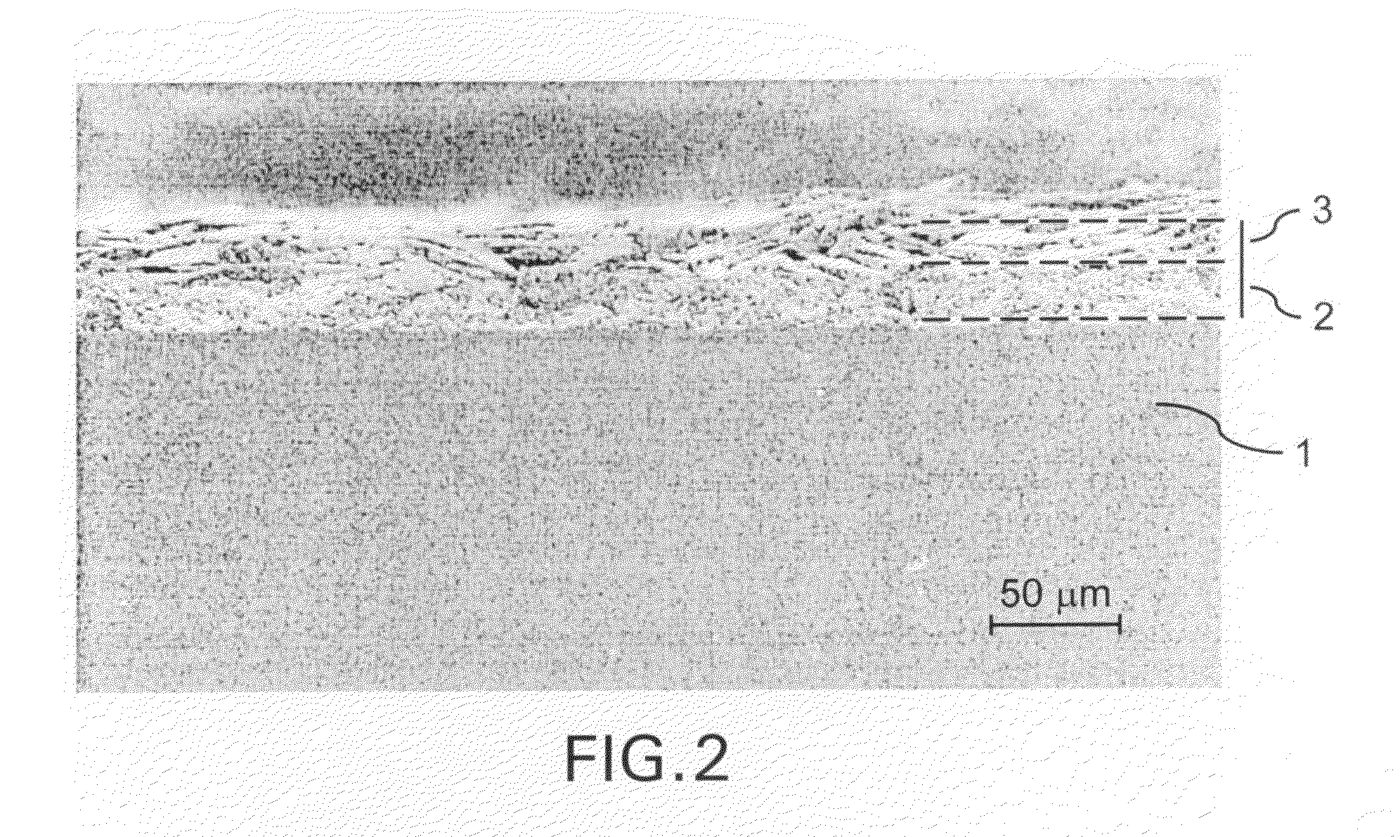
[0090]This produced a light gray glass ceramic cooktop with a metallic effect. The layer thickness of the silicone coating was 20±2 μm. The scratch resistance of the silicone layer applied to the underside was very low. The rounded hard metal spike (radius: 500 μm) was able to completely pen...
example 2
Counter-Example 2
Single-Layer Dark Gray Silicone Coating with Low Scratch Resistance
[0091]As in counter-example 1, a colorless glass ceramic plate smooth on both sides was coated on the underside with a silicone pigment having the composition (B) according to Table 2. The coating was dried for 45 min at 150° C.
[0092]This produced a dark gray glass ceramic cooktop with a metallic effect. The layer thickness of the silicone coating was 20±2 μm. The scratch resistance of the silicone layer applied to the underside was very low. The rounded hard metal spike (radius: 500 μm) was able to completely penetrate the layer system already at a load of 200 g so that the scratch trajectory was clearly visible to the user when viewing the cooktop from above.
example 3
Counter-Example 3
Single-Layer Crosslinked Silicone Coating with Low Scratch Resistance
[0093]As in counter-example 2, a colorless glass ceramic plate smooth on both sides was coated on the underside with a silicone pigment having the composition (B) according to Table 2. The coating was dried for 45 min at 150° C. and then fired for 4 h at 450° C.
[0094]This produced a dark gray glass ceramic cooktop with a metallic effect. The layer thickness of the silicone coating was 19±2 μm. The scratch resistance of the silicone layer applied to the underside was very low. The rounded hard metal spike (radius: 500 μm) was able to completely penetrate the layer system already at a load of 100 g so that the scratch trajectory was clearly visible to the user (viewing the cooktop from above).
PUM
| Property | Measurement | Unit |
|---|---|---|
| thickness | aaaaa | aaaaa |
| thickness | aaaaa | aaaaa |
| thickness | aaaaa | aaaaa |
Abstract
Description
Claims
Application Information