Power supply system

a power supply system and power supply technology, applied in the direction of parallel/serial switching, battery/fuel cell control arrangement, transportation and packaging, etc., can solve the problems of enlargement degradation of battery components, and achieve the effect of high charge, positive impact on the environment, and high level of charg

Active Publication Date: 2016-10-27
MANODYA LTD +1
View PDF10 Cites 8 Cited by
  • Summary
  • Abstract
  • Description
  • Claims
  • Application Information

AI Technical Summary

Benefits of technology

[0008]It has been found that this can improve the efficiency of the electrical battery. In particular, periodically switching between a discharge state and a rest state can increase the working time of the electrical battery in comparison to a system that involves continuous discharge. The efficiency of the battery can be increased further by supplying an electrical current during a rest period when the first electrical battery is in the rest state, when the battery is maintained at a high charge state.
[0044]The present invention relates to a pulse discharge system wherein the battery of a power supply system can be supplied with a current during the rest phase of the pulse discharge. This power supply system allows fora fixed voltage interval at a constant current more electrical power to be provided over a longer working time. Alternatively, for a fixed working time at a constant current more electrical power is provided with lower battery discharging.

Problems solved by technology

During discharge batteries may generate heat which can enhance degradation to battery components.

Method used


Image

  • Power supply system
  • Power supply system
  • Power supply system

Examples


Embodiment Construction

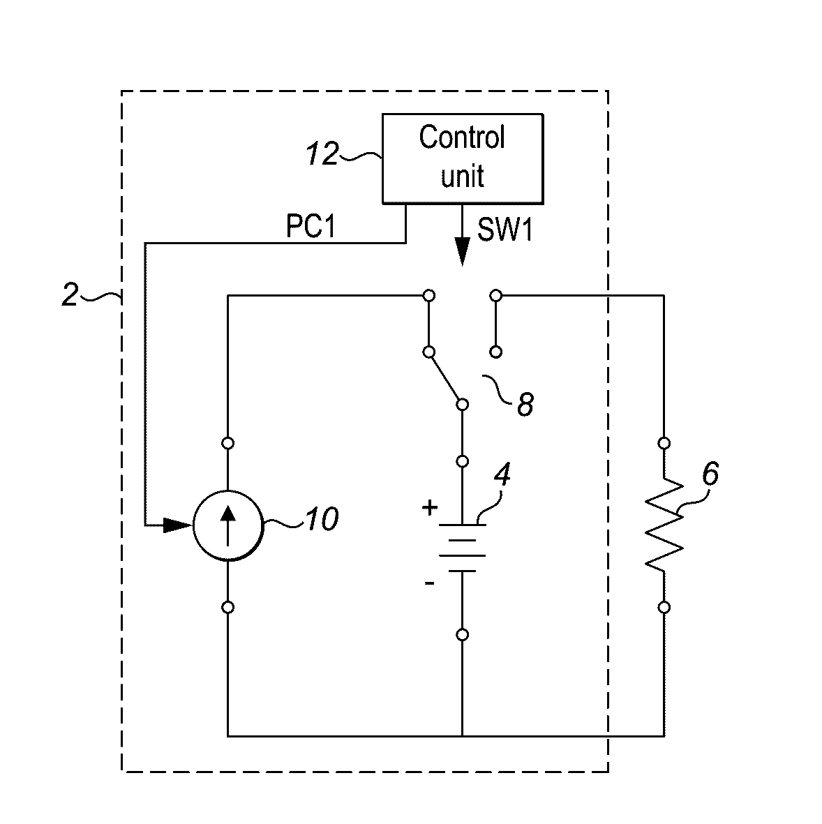
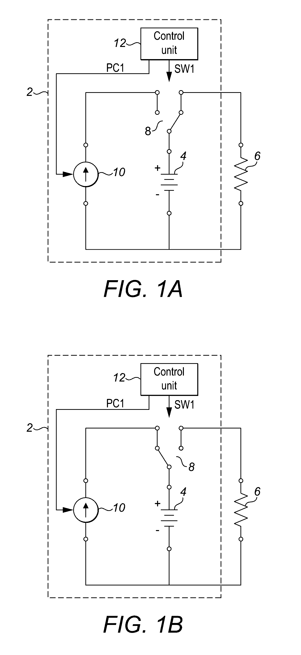
[0053]FIGS. 1A and 1B are simplified circuit diagrams of an example power supply system 2. The power supply system 2 includes a battery 4 which is connected in series to a load 6 by a two way switch 8. The power supply 2 system drives the load by supplying an electrical current. A power source 10 is connected to the other terminal of the two way switch 8. FIG. 1A shows the circuit in the configuration where the two-way switch 8 is connected to the load 6 so that the battery 4 supplies power to the load 6. FIG. 1B shows the alternative arrangement where the two way switch 8 is connected to the power source 10 so that the battery 4 can be recharged. The control unit 12 is configured to generate a switching signal SW1. The switching signal SW1 activates the switch 8 causing it to switch periodically between its two positions.

[0054]In FIG. 1A when the switch 8 is closed between the battery 4 and the load 6, current flows from the battery 4 to the load 6. This results in a discharge of t...


PUM


Abstract

A power supply system for supplying an electrical load using a pulse discharge arrangement. The power supply system comprises a first electrical battery for supplying said electrical load, a control unit configured to control the first electrical battery for periodically switching between a discharge state of the first electrical battery and a rest state of the first electrical battery, said control unit being further configured to control a power source for supplying a first charging current to the first electrical battery during a rest period when the first electrical battery is in the rest state.

Description

[0001]The invention relates to a power supply system comprising an electrical battery for supplying an electrical load. In particular, the invention relates to a power supply system and / or control system that can enhance the efficiency of operation of a battery.BACKGROUND[0002]Batteries are ubiquitous in modern day technology. Batteries are available in a wide range of types, each specialised for particular applications, from small button cell batteries used in watches, larger Li-ion batteries used in mobile devices, to large industrial scale batteries. There is often a trade-off between the physical size of the battery versus the capacity required for the battery's application, the two of which are directly related.[0003]An important subclass of batteries is rechargeable batteries, which provide the functionality of being able to be used repeatedly. Rechargeable batteries are the power source of choice for most portable applications, from cellphones and tablets, to electric motors ...

Claims


Application Information

Patent Timeline
Patent Type & Authority Applications(United States)
IPC IPC(8): H02J7/00H02J7/35
CPCH02J7/0024H02J7/345H02J7/35H02J7/007B60L58/18B60L58/21H02J7/0013H02J7/0063H02J7/0068H02J7/0069H02J7/00711Y02T10/70
Inventor MAGAGNIN, LUCATIRELLA, VINCENZO
Owner MANODYA LTD
Why Eureka
Try Eureka