Circuit for vehicle and circuit routing system for vehicle

a circuit routing and vehicle technology, applied in the direction of vehicle components, electric/fluid circuits, electrical apparatus, etc., can solve the problems of increasing the number of electrical components mounted on the vehicle, increasing the cost of components or manufacturing costs, and complicated structure of the wire harness routed on the vehicle body, etc., to achieve easy management or maintenance of the fuse, easy to bend, and simplify the structure of the wire harness as a whole

Active Publication Date: 2018-11-22
YAZAKI CORP
View PDF7 Cites 5 Cited by
  • Summary
  • Abstract
  • Description
  • Claims
  • Application Information

AI Technical Summary

Benefits of technology

[0008]In addition, in order to finish a wire harness with a predetermined routing shape in a work process of manufacturing the wire harness, a bundle of a large number of electric wires constituting the wire harness is routed for a long distance to extend along a preliminarily designated path. Thus, it takes long work time therefor. In addition, substantially all the electric wires are gathered in a trunk line portion of the wire harness. Accordingly, the number of the bundled electric wires is so large that the weight increases.
[0029]According to the circuit for the vehicle and the circuit routing system for the vehicle according to the present invention, a structure for electric connection between various electrical components and a power supply on a vehicle and among the electrical components, particularly the configuration of a trunk line portion, can be simplified and addition of a new electric wire is also easy.

Problems solved by technology

Recently, the structure of the wire harness routed on a body of a vehicle tends to be complicated with an increase of the number of electrical components mounted on the vehicle.
Therefore, it is difficult to commonize components constituting the wire harnesses to thereby result in an increase of the component cost or manufacturing cost.
Thus, it takes long work time therefor.
However, the structure or shape of the wire harness is complicated, and it is very difficult to add another electric wire to the existing wire harness afterwards.
In addition, it is unnecessary to connect the fuses to the branch lines or the respective electrical components.

Method used


Image

  • Circuit for vehicle and circuit routing system for vehicle
  • Circuit for vehicle and circuit routing system for vehicle
  • Circuit for vehicle and circuit routing system for vehicle

Examples


Embodiment Construction

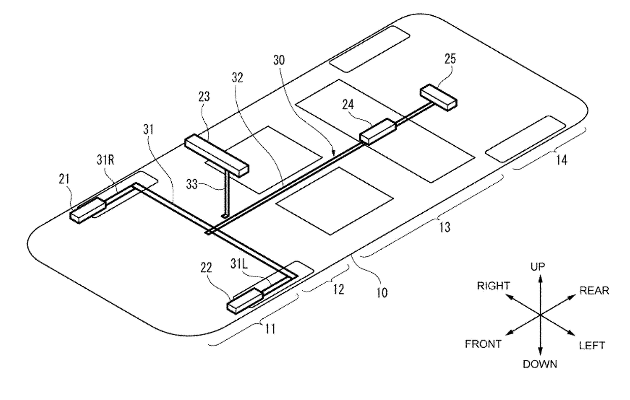
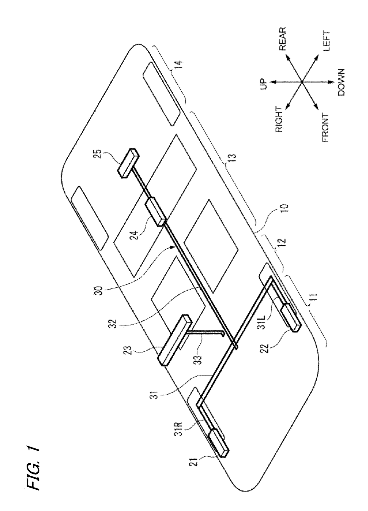
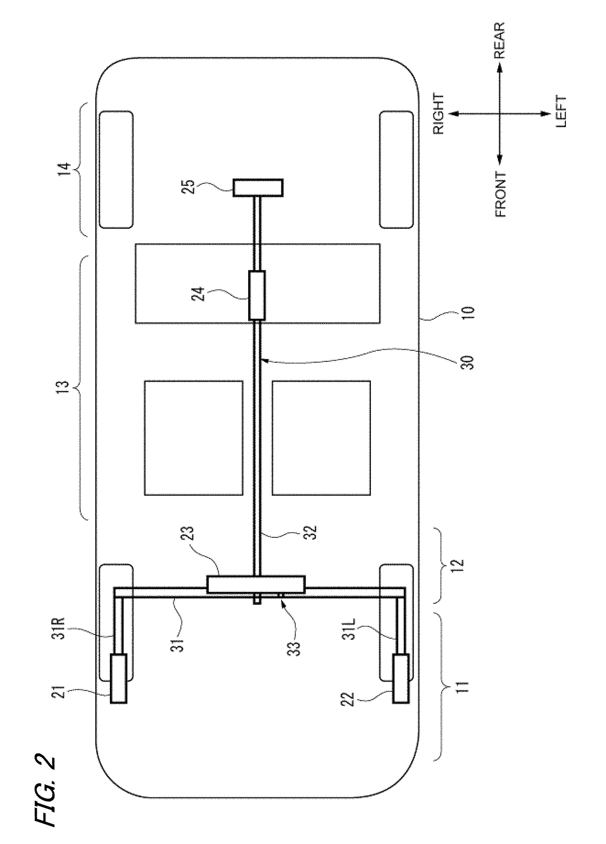
[0042]A specific embodiment about the present invention will be described below with reference to the respective drawings.

[0043]First, an outline of a circuit routing system for a vehicle will be described.

[0044]A layout of the circuit routing system for the vehicle on a vehicle body in the embodiment of the present invention is shown in FIG. 1 and FIG. 2.

[0045]The circuit routing system for the vehicle is used as a transmission line required for feeding power of a main power supply such as an on-vehicle battery respectively to accessories i.e. various electrical components at respective portions of the vehicle body or for performing exchange of signals among the electrical components. That is, the circuit routing system for the vehicle is similar to or the same as a general wire harness in function but largely different from the general wire harness in structure.

[0046]The circuit routing system for the vehicle shown in FIG. 1 and FIG. 2 is provided with a plurality of backbone JB (...


PUM


Abstract

This vehicle circuit routing system as a whole has a backbone-like routing structure, said system being provided with a plurality of backbone JB structures, wherein the vehicle circuit bodies of the backbone JB structures are connected to each other by means of a backbone main line. Each vehicle circuit body is provided with a power supply circuit that is connected to a main power supply on the vehicle, a plurality of connection parts to which a plurality of branch lines having a power supply line are connected, and a control unit that controls the distribution of power from the power supply circuit to the branch lines.

Description

CROSS REFERENCE TO RELATED APPLICATIONS[0001]This application is a continuation of PCT application No. PCT / JP2017 / 003493, which was filed on Jan. 31, 2017 based on Japanese patent application No. 2016-018404 filed on Feb. 2, 2016, whose contents are incorporated herein by reference. Also, all the references cited herein are incorporated as a whole.BACKGROUND OF THE INVENTION1. Technical Field[0002]The present invention relates to a circuit for a vehicle and a circuit routing system for the vehicle, that are routed on the vehicle.2. Background Art[0003]On a vehicle, power supply power has to be suitably fed, for example, from an alternator (power generator) or a battery that is a main power supply to each of a huge number of various electrical components. In addition, such a system used for feeding the power supply power also has to be provided with a function of switching ON / OFF the feeding of the power in accordance with necessity or a function for cutting off a current for each el...

Claims


Application Information

Patent Timeline
Patent Type & Authority Applications(United States)
IPC IPC(8): B60R16/023H02G3/16
CPCB60R16/023H02G3/16H02G3/083H02G3/00B60R16/0207B60R16/02
Inventor SAITO, YASUYUKISASAKI, NORIAKINAGANISHI, YUKINARIFURUTA, TAKU
Owner YAZAKI CORP
Why Eureka
Try Eureka