

Reducing turbocharged engine overheating
A turbocharger and engine technology, applied in engine components, combustion engines, engine control, etc., can solve the problem of not keeping the temperature of the cylinder head below the melting point of the engine metal
- Summary
- Abstract
- Description
- Claims
- Application Information
AI Technical Summary
Problems solved by technology
Method used
Image

Examples
Embodiment Construction
[0017] The present description relates to a method of deactivating one or more engine cylinders while limiting engine load in response to coolant loss in a turbocharged engine. In one example, the method includes deactivating one or more engine cylinders while limiting one or more active cylinder loads while maintaining engine speed below a threshold engine speed, and while maintaining engine cylinders below a third threshold temperature. In this manner, engine cylinder overheating may be mitigated while maintaining vehicle drivability and vehicle operability over a range of engine operating conditions.
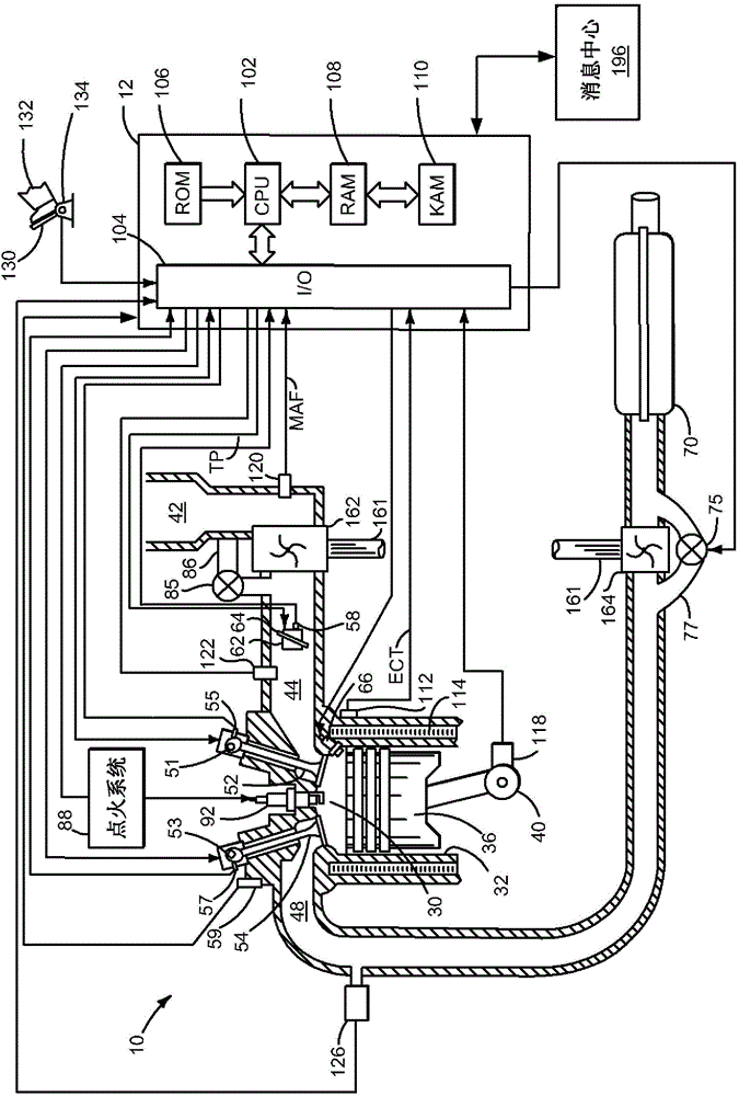
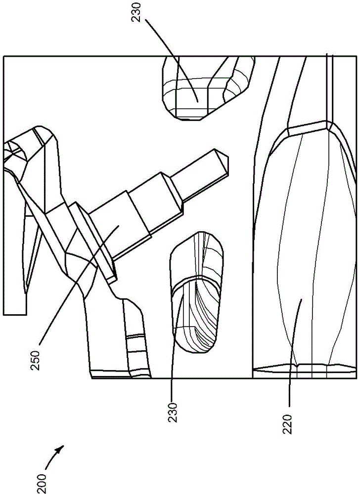
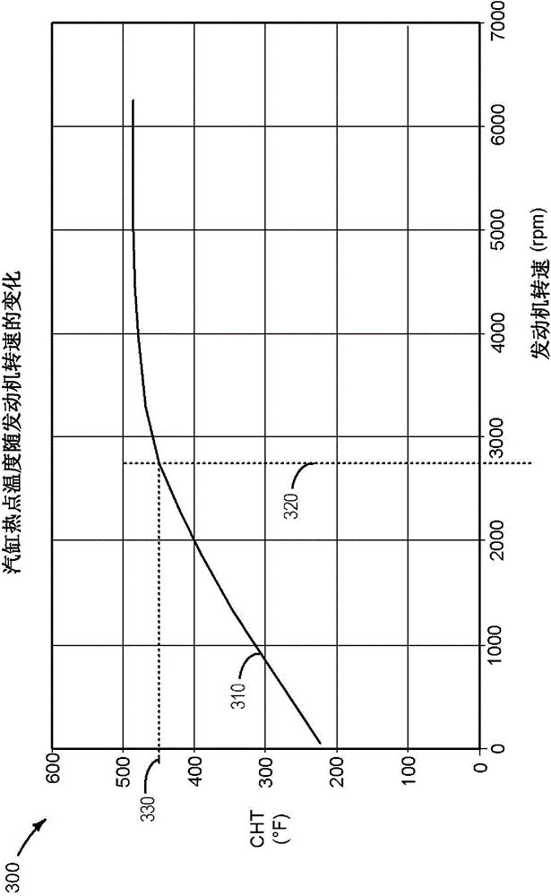
[0018] figure 1 An example of a turbocharged engine is shown, including an intake compressor, exhaust turbine, wastegate, and engine controller. figure 2 An example of an exhaust manifold temperature sensor that may be used to provide an indication of engine cylinder head temperature is shown. Figure 3-5 are example curves for cylinder head temperature versus engine speed...
PUM
 Abstract
Description
Claims
Application Information