Digital microscope apparatus, imaging method therefor, and program

A digital microscope and equipment technology, applied in the direction of microscope, image communication, TV, etc., can solve the problem of reduced accuracy

Inactive Publication Date: 2014-09-17
SONY CORP
View PDF3 Cites 8 Cited by
  • Summary
  • Abstract
  • Description
  • Claims
  • Application Information

AI Technical Summary

Problems solved by technology

Conversely, there is a possibility of reduced accuracy due to the si

Method used


Image

  • Digital microscope apparatus, imaging method therefor, and program
  • Digital microscope apparatus, imaging method therefor, and program
  • Digital microscope apparatus, imaging method therefor, and program

Examples


no. 1 approach

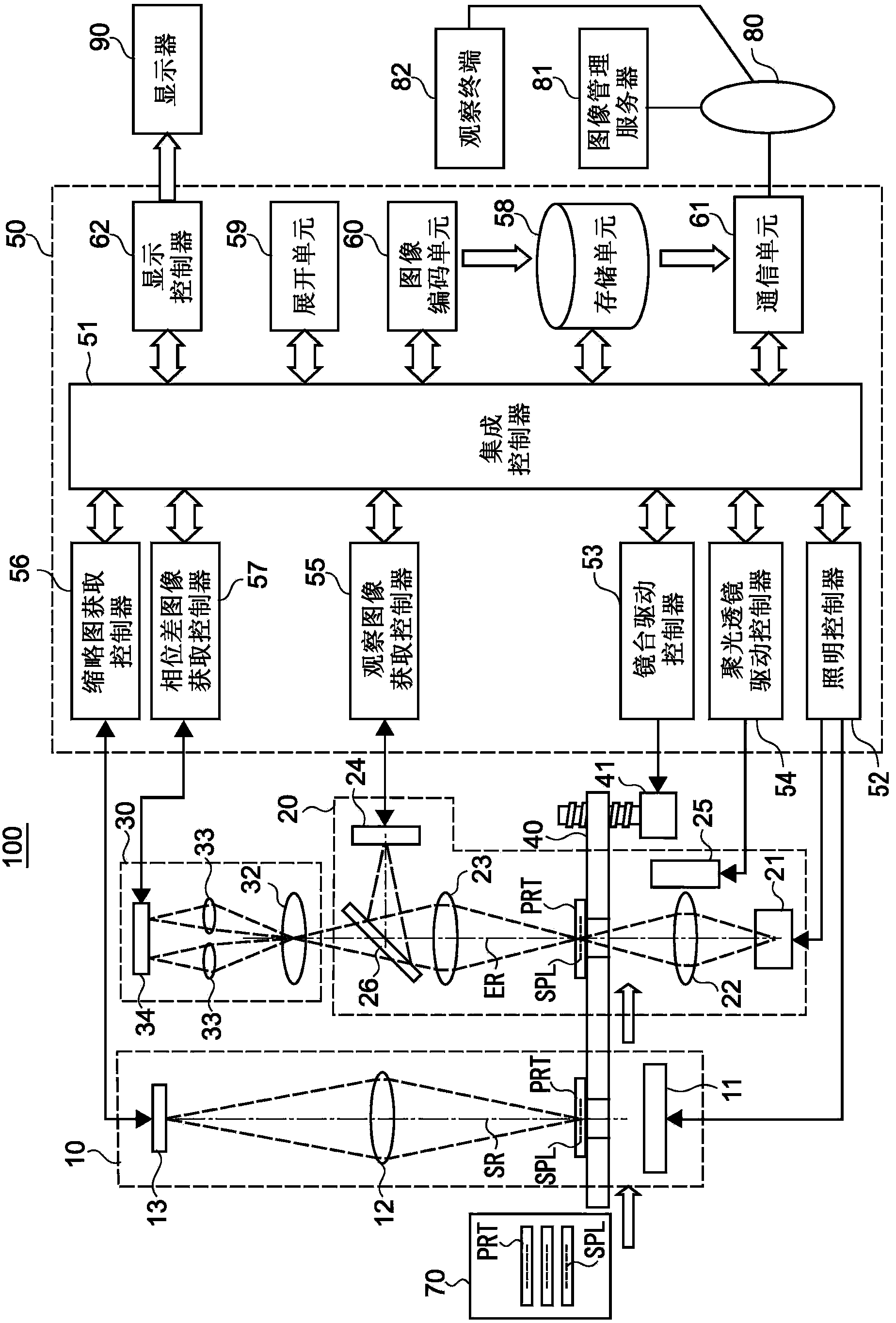
[0041] figure 1 is a diagram showing the overall configuration of the digital microscope apparatus 100 according to this embodiment.

[0042] (overall configuration)

[0043] The digital microscope device 100 includes a thumbnail image acquisition unit 10 , an observation image acquisition unit 20 , a phase difference image acquisition unit 30 , a stage 40 , and a controller 50 .

[0044] The thumbnail image acquisition unit 10 acquires an overall image of the preparation PRT on which the sample SPL is set (this image is hereinafter referred to as "thumbnail image").

[0045] The observation image acquisition unit 20 acquires an image obtained by enlarging the sample SPL set on the preparation PRT at a predetermined magnification (hereinafter, the image is referred to as “observation image”).

[0046]The phase difference image acquisition unit 30 acquires a phase difference image containing information on the amount and orientation of displacement in the optical axis directi...

Deformed example 1

[0172] In the above-described embodiment, when it is determined that the blurred boundary portion exists between n small regions continuously arranged in a predetermined one axial direction (x-axis or y-axis direction), the imaging range in one axial direction becomes within The imaging range of the initial imaging is 1 / m, and a small area is imaged again through m times of imaging. Instead of such control, a control operation of tilting the stage 40 or observing the optical system of the image acquisition unit 20 to cancel the tilt of the sample SPL may be performed.

[0173] Alternatively, in the case where the sample SPL is partially tilted, a control operation of tilting the stage 40 or observing the optical system of the image acquisition unit 20 to partially cancel the tilt may be performed at an appropriate position.

[0174] Figure 11 It is an example diagram of re-imaging by Modification 1. Such as Figure 11 As shown in , tilt the stage 40 or observe the optical ...

Deformed example 2

[0176] For the evaluation area in the observed image, in the first embodiment, such as Figure 5 As shown in , an evaluation area is set at the middle of each of the four sides of the small area. However, the present disclosure is not limited thereto. Such as Figure 12 As shown in , evaluation areas A1 to A4, B1 to B4, C1 to C4, D1 to D4, and E1 to E4 may be set at the four corners of the small areas A, B, C, D, and E, respectively. In this case, there are two pairs of the two nearest evaluation regions among adjacent small regions in the connected image, in the case of small regions A and B, ie, A3 and B1 and A4 and B2. When the absolute value of the difference in edge density between A3 and B1 is given by |Δd A3-B1 | is represented and the absolute value of the difference in edge density between A4 and B2 is given by |Δd A4-B2 | means and in (|Δd A3-B1 |+|Δd A4-B2 When |) / 2>ε, the boundary part between the small area A and the small area B is determined as the fuzzy b...


PUM


Abstract

A digital microscope apparatus includes: an observation image capturing unit configured to capture an observation image of each of a plurality of small areas, an area containing a sample on a glass slide being partitioned by the plurality of small areas; and a controller configured to set at least one evaluation area for the observation image of each of the plurality of small areas, the observation image being captured by the observation image capturing unit, to perform an edge detection on the at least one evaluation area, and to calculate, using results of the edge detection on two evaluation areas that are closest between two of the observation images adjacently located in a connected image, a difference in blur evaluation amount between the two observation images, the connected image being obtained by connecting the observation images according to the partition.

Description

[0001] Cross References to Related Applications [0002] This application claims the benefit of Japanese Priority Patent Application JP2013-050520 filed on Mar. 13, 2013, the entire contents of which are hereby incorporated by reference. technical field [0003] The present disclosure relates to a digital microscope device that acquires an enlarged image of a sample such as a biological sample as an observation image, and an imaging method and program for the digital microscope device. Background technique [0004] In the past, in order to observe the entire sample using digital microscope equipment, images of small areas of the area containing the sample on the segmented glass slide were acquired by magnifying the imaging system, and this image of the corresponding small areas was concatenated with each other to generate one large image . [0005] For a focusing system in which the objective lens of the magnifying imaging system is focused on the pathological sample used a...

Claims


Application Information

Patent Timeline
IPC IPC(8): G02B21/36G02B21/24G02B7/28G01N21/84
CPCG02B21/18G02B7/34G02B21/0016G02B7/36H04N7/183G02B21/14G02B21/245G02B21/00G02B21/244G02B21/367
Inventor 松延刚
Owner SONY CORP
Why Eureka
Try Eureka