Variable inductor, voltage controlled oscillator and phase locked loop incorporating the variable inductor

An inductor and variable technology, applied in the direction of a single resonant circuit with only variable inductance/capacitance, a single resonant circuit with variable inductance and capacitance at the same time, variable inductance/transformer, etc. The capacitor diode cannot stimulate the VCO oscillation and other problems

Active Publication Date: 2017-03-01
TAIWAN SEMICON MFG CO LTD
View PDF4 Cites 0 Cited by
  • Summary
  • Abstract
  • Description
  • Claims
  • Application Information

AI Technical Summary

Problems solved by technology

In some cases, if the Q factor is too low, the varactor cannot excite the oscillation in the VCO, which will prevent the PLL from locking the output signal to the reference signal

Method used


Image

  • Variable inductor, voltage controlled oscillator and phase locked loop incorporating the variable inductor
  • Variable inductor, voltage controlled oscillator and phase locked loop incorporating the variable inductor
  • Variable inductor, voltage controlled oscillator and phase locked loop incorporating the variable inductor

Examples


Embodiment Construction

[0035] In order to realize the different features of the present invention, the following invention provides many different embodiments or examples. Specific examples of components and arrangements are described below to simplify the present disclosure. These are examples and not intended to be limiting.

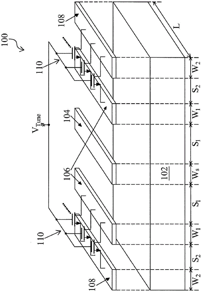
[0036] figure 1 is a perspective view of a variable inductor 100 in accordance with one or more embodiments. The variable inductor 100 includes a substrate 102 and a signal line 104 disposed over the substrate and extending in a first direction. The signal line 104 is configured to receive a DC operating voltage and a signal. A pair of floating planes 106 is disposed above the substrate 102 and extends parallel to the signal line 104 in a first direction. Each of the pair of floating planes 106 is configured to be electrically floating. The floating planes of the pair of floating planes 106 are provided on both sides of the signal line 104 . A pair of ground planes 108...


PUM


Abstract

The invention discloses a variable inductor, a voltage-controlled oscillator containing the variable inductor and a phase-locked loop, wherein the variable inductor includes a signal line arranged above a substrate. The variable inductor also includes: a first ground plane located above the substrate, the first ground plane disposed on the first side of the signal line; and a second ground plane disposed above the substrate, the second ground plane disposed on the signal line on the second side of the signal line opposite the first side of the line. The variable inductor further includes: a first floating plane located above the substrate, the first floating plane disposed between the first ground plane and the signal line; and a second floating plane located above the substrate, the second The floating plane is arranged between the second ground plane and the signal line. The variable inductor also includes an array of switches configured to selectively connect the first ground plane to the first floating plane, and selectively connect the second ground plane to the second floating plane.

Description

technical field [0001] The present invention generally relates to the semiconductor field, and more specifically, relates to a variable inductor, a voltage-controlled oscillator and a phase-locked loop including the variable inductor. Background technique [0002] A phase locked loop (PLL) is a control system configured to generate an output signal whose phase is related to that of a reference signal. PLLs are used in demodulator systems, tone detectors, and frequency synthesizers. PLLs are also used in digital applications involving high frequency periodic signals to synchronize events within a circuit. [0003] The PLL includes a voltage controlled oscillator (VCO) configured to adjust the frequency of the output signal based on the control signal. In some cases, the VCO includes varactor diodes. Varactor diodes are diodes with variable capacitance. In some cases, metal oxide semiconductor (MOS) varactor diodes are used in the VCO. In some cases, VCOs for high-frequen...

Claims


Application Information

Patent Timeline
Patent Type & Authority Patents(China)
IPC IPC(8): H01L23/522H01L23/64H03B5/18H03L7/08
CPCH01F2021/125H03B5/1228H03B5/1212H03B5/1256H03B2201/0216H03J3/20H03J3/22
Inventor 刘懿萱谢协宏周淳朴薛福隆
Owner TAIWAN SEMICON MFG CO LTD
Why Eureka
Try Eureka