Pressure relief device for power distribution cabinets

A technology of pressure relief device and power distribution cabinet, which is applied in the substation/power distribution device shell, cooling/ventilation of substation/switchgear, etc., and can solve problems such as poor heat dissipation, unfavorable long-life and safe operation of equipment, and temperature rise

Inactive Publication Date: 2014-09-17
XIANGYUAN SHUYUAN ELECTRICAL APPLIANCE
View PDF5 Cites 3 Cited by
  • Summary
  • Abstract
  • Description
  • Claims
  • Application Information

AI Technical Summary

Problems solved by technology

However, because the pressure relief device with this design is a sealed design, its heat dissipation effect is very poor under normal operating conditions, and the temperature rise is relatively high under heavy load conditions, which is not conducive to the long-life and safe operation of the equipment.

Method used


Image

  • Pressure relief device for power distribution cabinets
  • Pressure relief device for power distribution cabinets

Examples


Embodiment Construction

[0010] The specific embodiments of the present invention will be further described below in conjunction with the accompanying drawings.

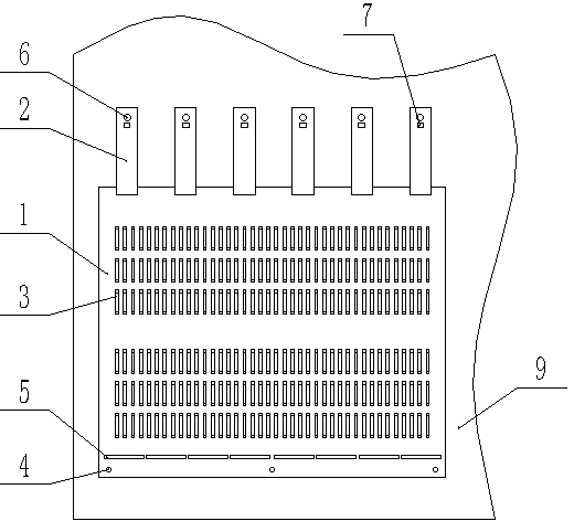
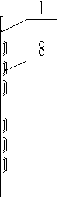
[0011] Such as figure 1 As shown, the pressure relief device of the power distribution cabinet includes a pressure relief plate 1 and a pressure strip 2. The pressure relief plate 1 is installed on the top of the low-voltage power distribution cabinet, and one side of the pressure relief plate 1 is fixed on the low-voltage power distribution cabinet. The pressure relief plate 2 One end is fixed on the low-voltage power distribution cabinet, and the other end is pressed on the other side of the pressure relief plate 1 to fix the pressure relief plate 1 . The pressure relief plate 1 is also provided with a plurality of ventilation holes 3 . The pressure relief plate 1 adopts a top-mounted structure, which is convenient for the hot air in the low-voltage power distribution cabinet to rise and dissipate heat, thereby improving the heat dissipati...


PUM


Abstract

The invention relates to a pressure relief device, in particular to a pressure relief device for power distribution cabinets. The pressure relief device for the power distribution cabinets is simple and reasonable in structure, safe and reliable to use and good in heat dissipation effect. According to the technical scheme, the pressure relief device comprises a pressure relief plate and pressing bars; the pressure relief plate is installed on the top of a low voltage power distribution cabinet, one side of the pressure relief plate is fixed to the low voltage power distribution cabinet, one ends the pressing bars are fixed to the low voltage power distribution cabinet, and the other ends of the pressing bars press the other side of the pressure relief plate to fix the pressure relief plate; the pressure relief plate is provided with a plurality of air holes, one side of the pressure relief plate is provided with first bolt holes, and the pressure relief plate is further provided with a plurality of rectangular through holes in the arrangement direction of the first bolt holes; one ends of the pressing bars are provided with second bolt holes, and the pressing bars are further provided with square holes located in the outer sides of the second bolt holes. The pressure relief device is simple and reasonable in structure and safe and reliable to use, and is widely applied to the power distribution cabinets.

Description

technical field [0001] The invention relates to a pressure relief device, in particular to a pressure relief device for a power distribution cabinet. Background technique [0002] At present, the pressure relief plate of the existing low-voltage power distribution cabinet usually adopts a closed plate, and one side is fixed by steel fasteners, and the other side is fixed by plastic screws. When an internal fault occurs, the high-temperature gas and air pressure will force the plastic screw to break or melt, and the pressure relief plate will open accordingly, thus playing a protective role. However, since the pressure relief device with this design is a sealed design, its heat dissipation effect is very poor under normal operating conditions, and the temperature rise is relatively high under heavy load conditions, which is not conducive to the long-life and safe operation of the equipment. Contents of the invention [0003] The invention overcomes the shortcomings of the ...

Claims


Application Information

Patent Timeline
IPC IPC(8): H02B1/26H02B1/56
Inventor 赵树元
Owner XIANGYUAN SHUYUAN ELECTRICAL APPLIANCE
Why Eureka
Try Eureka