Tail structure of linear motor

A linear motor and mover technology, applied in electrical components, electromechanical devices, electric components, etc., can solve problems such as easily damaged motor movers, reduced motor stability, and reduced motor efficiency.

Inactive Publication Date: 2014-09-17
杨超
View PDF3 Cites 0 Cited by
  • Summary
  • Abstract
  • Description
  • Claims
  • Application Information

AI Technical Summary

Problems solved by technology

It has been disclosed that when the mover of the linear motor goes down, it directly makes rigid contact with the end, which not only reduces the stability of the motor, but also easily damages the mover of the motor
In addition, since the mover runs inside the lower protective tube, the temperature inside the lower protective tube of the mover is likely to be too high, affecting the magnetic properties of the mover and reducing the efficiency of the motor

Method used


Image

  • Tail structure of linear motor

Examples


Embodiment Construction

[0010] The present invention will be further described below in conjunction with the accompanying drawings and embodiments.

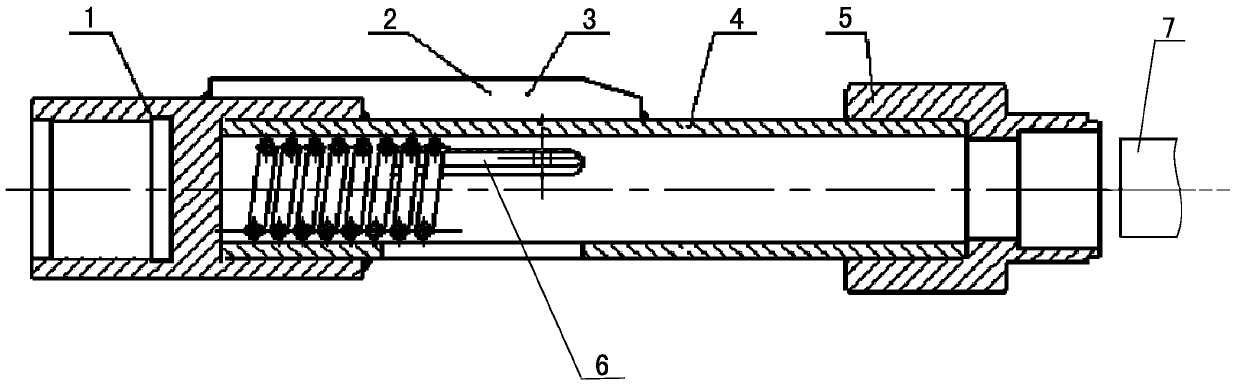
[0011] See figure 1 The shown tail structure of a linear motor includes a protective tube 4 at the lower end of the mover, and one end of the protective tube at the lower end of the mover is connected to a terminal 5 connected to the stator. In this embodiment, a buffer spring 3 is installed in the protective tube 4 at the lower end of the mover. One end of the buffer spring 3 is connected to the spring seat 1 installed at the other end of the protective tube 4 at the lower end of the mover. The other end of the buffer spring 3 acts on the motor. Motor sub 7 one ends. In the present invention, after the spring seat 1 and the protective tube 4 at the lower end of the mover are threaded, the connection strength is ensured, and the outer circular surfaces of the protective tube 4 at the lower end of the mover and the spring seat 1 are provided with There...


PUM


Abstract

The invention discloses a tail structure of a linear motor. The tail structure comprises a rotor lower end protection pipe, and one end of the rotor lower end protection pipe is connected with a stator tail connection end. A buffer spring is installed in the rotor lower end protection pipe, and one end of the buffer spring is connected with a spring seat installed at the other end of the rotor lower end protection pipe. The rotor lower end protection pipe is provided with a heat-dissipating through groove communicated with the external. Through the spring in the rotor lower end protection pipe, the phenomena that a rotor of the linear motor directly makes rigid contact with the end when moving downwards and the rotor of the motor is damaged can be avoided. In addition, through the heat-dissipating through groove in the rotor lower end protection pipe, the interior of the rotor lower end protection pipe is communicated with the exterior, and therefore the phenomena that the temperature in the protection pipe is excessively high, the magnetism of the rotor is influenced and the efficiency of the motor is lowered can be avoided.

Description

technical field [0001] The invention relates to a linear motor for oil extraction, and is particularly suitable for a tail structure of the linear motor. Background technique [0002] At present, due to the needs of oil production engineering in oil fields, the technology of oil production equipment has been continuously developed and improved. As a new type of oil production equipment, linear motors have become new energy-saving equipment that saves costs. It has been disclosed that when the mover of the linear motor goes down, it directly makes rigid contact with the end, which not only reduces the stability of the motor, but also easily damages the mover of the motor. In addition, since the mover runs inside the lower protective tube, the temperature inside the lower protective tube of the mover is likely to be too high, affecting the magnetic properties of the mover and reducing the efficiency of the motor. Contents of the invention [0003] In view of the above situa...

Claims


Application Information

Patent Timeline
IPC IPC(8): H02K41/02
Inventor 杨超
Owner 杨超
Why Eureka
Try Eureka