condiment carousel
A condiment and turntable technology, which is applied in the field of kitchen racks, can solve the problems of inconvenient use, tilting seasoning container bottles, and difficulty in seeing the variety of seasonings, etc., to ensure safety and simplicity, small covering area, and convenient operation Effect
- Summary
- Abstract
- Description
- Claims
- Application Information
AI Technical Summary
Problems solved by technology
Method used
Image
Examples
Embodiment 1
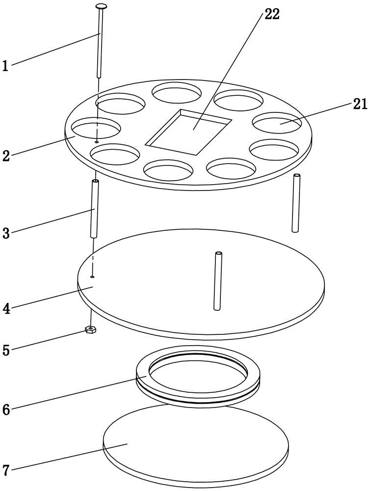
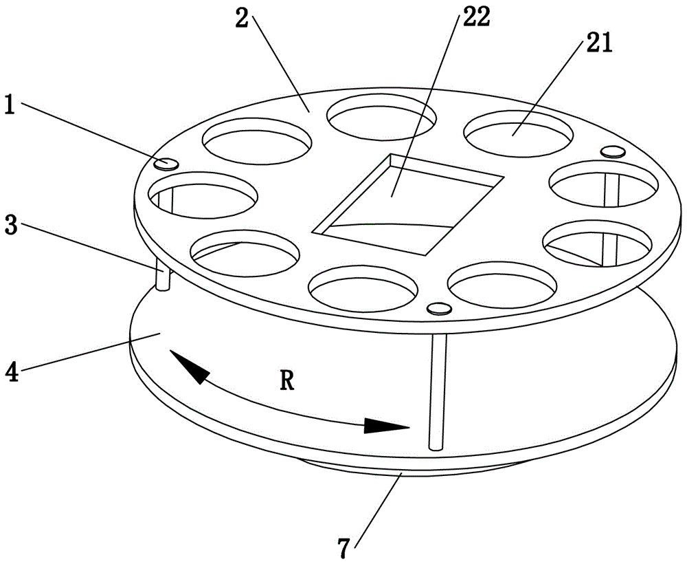
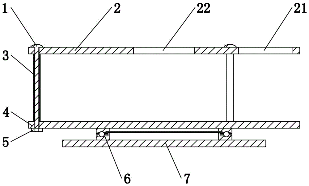
[0032] Embodiment one, see Figure 1 to Figure 3 As shown, a condiment turntable includes a rotating set of bearing tray 4, a limit plate 2 and a support member, the limit plate 2 is received above the support tray 4 through the support member, and the surface of the limit plate 2 is provided with more than four Positioning holes 21 (nine positioning holes 21 are provided in this embodiment, generally 6-12 positioning holes in practical applications), each positioning hole 21 is arranged in a ring.
[0033] When in use, put various seasonings (condiments refer to containers for putting oil and seasonings) into a positioning hole 21 respectively, and the supporting tray 4 plays a supporting role for the seasonings, while the positioning holes 21 limit the seasoning. The location of the condiments can also avoid the condiments from tilting. At the same time, different condiments have their own independent storage space, and the partitions are obvious. Since the condiments are d...
Embodiment 2
[0040] Embodiment two, the difference with embodiment one is: see Figure 4 with Figure 5 As shown, the size of each positioning hole 21 of the limiting plate 2 is consistent, but because the profile of the condiment is large or small, when the profile (diameter) of the condiment is very small, it is placed in the positioning hole 21, and the positioning hole 21 will vacate a lot Empty, condiments are easy to tilt, and even fall out of the support tray 4 after tilting, so a shrinkage cavity sleeve 8 is added in the positioning hole 21. The shrinkage cavity sleeve 8 is composed of a support surface 82 and a top ring protrusion 83. The support surface 82 is provided with The central hole 81 and the top ring protrusion 83 are arranged at the bottom of the support surface 82 and correspond to the inner wall of the positioning hole 21 of the limit plate 2. The top ring protrusion 83 is inserted into the positioning hole 21, and the edge of the support surface 82 is placed on the p...
Embodiment 3
[0042] Embodiment three, the difference with embodiment two is: see Image 6 As shown, when the diameter and height of the condiment are very small, the condiment cannot be placed in the positioning hole 21 of the limiting plate 2, so adding a shrinkage cavity sleeve 8 in the positioning hole 21 can overcome the problem of placing the condiment when the diameter is small. In addition, a coaming plate 84 is provided at the bottom of the central hole 81 of the shrinkage cavity sleeve 8, and a supporting flange 85 is provided on the inner side of the lower end of the coaming plate 84. When the seasoning is put into the central hole 81, it can be raised by the supporting flange 85. , so that the condiment is exposed outside the top surface of the limiting disc 2 .
[0043] The bottom of the shrinkage cavity sleeve 8 is open for easy cleaning.
[0044] The shrinkage hole sleeve 8 is plugged and matched with the positioning hole 21, see Image 6 As shown by the arrow in middle A, ...
PUM
 Abstract
Description
Claims
Application Information
 - R&D
- Intellectual Property
- Life Sciences
- Materials
- Tech Scout
- Unparalleled Data Quality
- Higher Quality Content
- 60% Fewer Hallucinations
Browse by: Latest US Patents, China's latest patents, Technical Efficacy Thesaurus, Application Domain, Technology Topic, Popular Technical Reports.
© 2025 PatSnap. All rights reserved.Legal|Privacy policy|Modern Slavery Act Transparency Statement|Sitemap|About US| Contact US: help@patsnap.com


