Posterior scleral reinforcement device and posterior scleral reinforcement method

A technology of posterior sclera reinforcement and sclera, which is applied in ophthalmic surgery, eye implants, etc., can solve problems such as detachment, vision loss, and easy displacement of the fixation belt, and achieve high reliability, reduce diopter, and shorten the axial length of the eye.

Active Publication Date: 2014-09-24
GUANGZHOU VISBOR BIOTECHNOLOGY LTD
View PDF4 Cites 1 Cited by
  • Summary
  • Abstract
  • Description
  • Claims
  • Application Information

AI Technical Summary

Problems solved by technology

[0002] Myopia will cause the eyeball's axial length to grow, and the retina will be easily pulled, causing retinal splitting or detachment. The surface of the posterior sclera is often accompanied by staphyloma, which makes the retina more likely to detach, resulting in vision loss
[0003] The current practice is to implant a fixation belt in the posterior sclera, and the fixation belt is easy to shift and lose its fixation effect clinically.

Method used


Image

  • Posterior scleral reinforcement device and posterior scleral reinforcement method
  • Posterior scleral reinforcement device and posterior scleral reinforcement method
  • Posterior scleral reinforcement device and posterior scleral reinforcement method

Examples


Embodiment 1

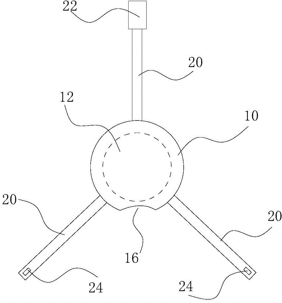
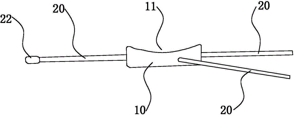
[0043] Such as Figure 1 to Figure 3 As shown, the posterior sclera reinforcement device includes a support pad 10 and a plurality of support straps 20. The inner side of the support pad 10 is a pressure side, and the pressure side has an arc-shaped inner concave surface 11. The inner ends of each support strap 20 are connected to the support pad 10 connected.

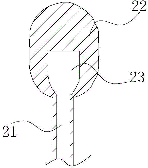
[0044] Wherein, the outer edge of the support pad 10 is circular, and there are three support straps 20, the inner ends of which are all connected to the periphery of the support pad 10, and the angle between two adjacent support straps 20 is 120 degrees. One of the filling pipes 21 is arranged in one of the support bands 20, and the end of the support band 20 that fills the pipe 21 is provided with a colloid end 22, and an injection cavity 23 is arranged in the colloid end 22; The outer end of the strap 20 is provided with fixing holes 24 .

[0045] The support pad 10 is an elastic body with a hollow inside to form ...

Embodiment 2

[0056] Such as Figure 5 As shown, in this embodiment, relative to Embodiment 1, the support pad 10 includes an outer colloid body 13 made of medical silica gel and a sheet-shaped inner support body 14 made of a medical titanium alloy. 13 wraps the inner support body 14 as a whole. The pressing side of the support pad 10 has an arc-shaped convex surface. The thickness of the inner support body 14 is less than 200um, and the inner support body 14 extends into one of the support bands 20 to form a support inner strip 141; a blood vessel passage hole 15 is provided on the support pad 10, and the blood vessel passage hole 15 runs through the support pad On the inside and outside of 10, the blood vessel passage hole 15 includes a large hole at the center of the support pad and small holes around the large hole.

[0057] Compared with Embodiment 1, this embodiment has the following advantages:

[0058] 1. A blood vessel passage hole 15 is provided on the support pad 10, and the b...


PUM


Abstract

The invention discloses a posterior scleral reinforcement device and a posterior scleral reinforcement method. The posterior scleral reinforcement device comprises a support pad and at least two support tapes, wherein the inner side of the support pad is a pressing side, the inner end of each support tape is connected with the support pad, a gap part is arranged on the edge of the support pad, and the gap part is positioned between the two support tapes. The posterior scleral reinforcement device and the posterior scleral reinforcement method are used for shortening the length of optic axis of a macular area, reducing the diopter and playing the role of adjusting the eye axis of an eyeball, and are also used for treating high myopia and high myopia with posterior scleral staphyloma, retinoschisis, retinal hole or retinal detachment, and besides, the support pad cannot cause displacement or detachment easily, can fix the posterior scleral in a long term, and has higher reliability, and the optic nerves can be avoided squeezing by means of the gap part.

Description

technical field [0001] The invention relates to a posterior sclera reinforcement device and a posterior sclera reinforcement method. Background technique [0002] Myopia will increase the axial length of the eyeball, and the retina will be easily pulled, causing retinal splitting or detachment. The surface of the posterior sclera is often accompanied by staphyloma, which makes the retina more likely to detach, resulting in vision loss. [0003] The existing method is: implant a fixation band in the posterior sclera, and the fixation band is easily displaced clinically and loses its fixation effect. [0004] The same problem exists for patients with retinal breaks etc. Contents of the invention [0005] Based on this, the present invention aims to overcome the defects of the prior art, and provides a posterior sclera reinforcement device and a posterior sclera reinforcement method. The present invention is used to shorten the axial length of the macula, reduce the diopter,...

Claims


Application Information

Patent Timeline
Patent Type & Authority Applications(China)
IPC IPC(8): A61F9/007A61F2/14
Inventor 不公告发明人
Owner GUANGZHOU VISBOR BIOTECHNOLOGY LTD
Why Eureka
Try Eureka