Tool marking method

A tool and marking technology, applied in the field of tool identification, can solve the problems of discarded packaging containers, unclear tool-related information, damaged labels and stickers, etc., and achieve the effect of facilitating management and maintenance

Inactive Publication Date: 2014-09-24
JIN XIANG KAI IND
View PDF8 Cites 5 Cited by
  • Summary
  • Abstract
  • Description
  • Claims
  • Application Information

AI Technical Summary

Problems solved by technology

[0005] However, the packaging container is discarded because the tool is taken out for use; the label sticker is torn off the tool and damaged, resulting in unclear information about the tool and relatively delaying the timeliness of maintenance

Method used


Image

  • Tool marking method
  • Tool marking method
  • Tool marking method

Examples


Embodiment Construction

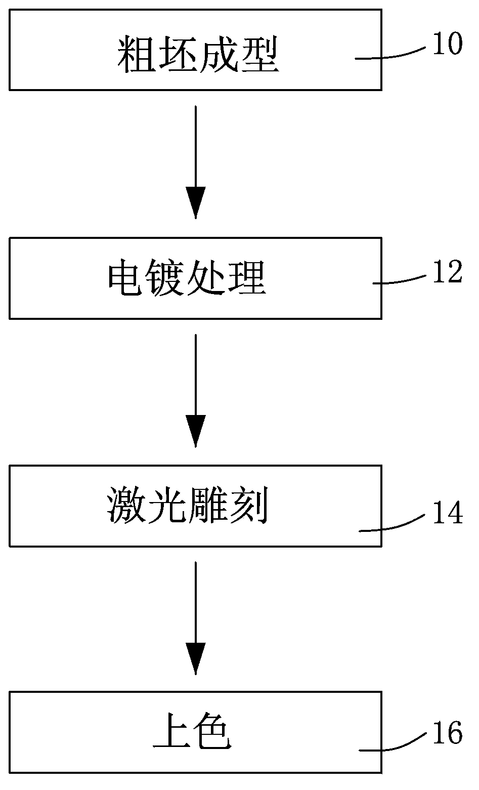
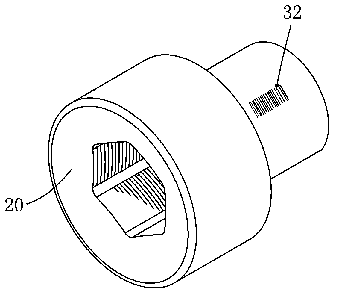
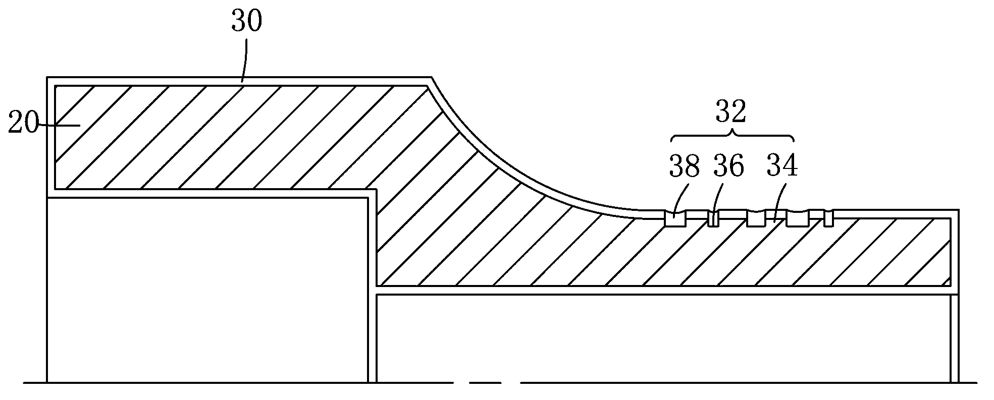
[0031] See figure 1 , To clarify the tool making process, starting from a rough embryo forming 10, going through the steps of electroplating 12 and laser engraving 14, until coloring 16, to complete the tool with barcode. In order to help readers understand the production process, the next interview will take the sleeve as an example. figure 2 , image 3 Explain in detail.

[0032] In the 10 steps of forming the rough embryo, the metal material uses high-pressure molding, cutting or forging equipment and machines to produce the rough embryo 20. The rough embryo 20 has the outline of the sleeve and includes a latch. The latch has a quadrilateral recessed structure. The concavity and convexity fit on the protruding part of the wrench; the set part and the set part are mostly hexagonal recessed structures, which can accommodate screwdriver heads, bolts or nuts of the same size.

[0033] In the 12 steps of the electroplating treatment, a layer of other metal is usually spread on the s...


PUM


Abstract

The invention relates to a tool marking method. A thick blank provided with a tool contour is provided; an electroplated coating wrapping the thick blank is provided; a bar code is provided, a plurality of recessed parts are formed in the surface of the thick blank by laser, and a bulge of the thick blank is reserved between two adjacent recessed parts; and a coloring material filling the recessed parts is provided. A tool completed according to the procedures can be conveniently stored, managed and maintained by scanning the bar code of the tool through a bar-code scanner.

Description

Technical field [0001] The present invention relates to tool identification technology, in particular to a method for making one-dimensional or two-dimensional bar codes on tools. Background technique [0002] There are many kinds of tools, such as: knives, shovel, planer, saw, axe, chisel, clamp, drill, file, rake, hammer, pliers, wrench, screwdriver, connecting rod, socket and screwdriver bit. These tools are based on the source of power. Electric, pneumatic, and manual tools can be distinguished. With international specifications such as metric or imperial systems, various tools are derived. It is very difficult to quickly search for suitable tools to use. Moreover, it is not conducive to the implementation of tool warehouse management. [0003] In order to solve the problem of searching for tools, the applicant in this case provided a tool. Rolling marks (such as dimensions) on the surface of the tool. After heat treatment, the recessed mark is filled with a non-conductive pri...

Claims


Application Information

Patent Timeline
Patent Type & Authority Applications(China)
IPC IPC(8): B23K26/362B23K26/70
CPCB23K26/361B23K26/702
Inventor 林大森
Owner JIN XIANG KAI IND
Why Eureka
Try Eureka